Background
The continuous increase in food
demand requires a rapid improvement in food production technologies. Food
insecurity is a major challenge in developing countries. Agriculture in
Ethiopia is mainly rain fed. Global warming has led to climate changing thus
rendering the rain fed agricultural systems unreliable. This has resulted on
more land being put under irrigation to meet the food demand for the growing
population.
In agriculture, one of the most
important jobs is to watering the farming land. Most of the farmers use the
manual control over the land that is to monitor the pumping or watering the
land by visiting the site. This will surely need more and more labor and as a
result the efficiency of work may be degraded. An automatic system can be
developed to monitor all the controlling operation. Automatic control system
reduces the human labor and increase the efficiency of the corresponding work.
In this project, an automatic
control system is introduced for watering the land by measuring the humidity or
in other word the temperature. The system measures the humidity of the soil and
depending upon the condition it will provide the needed water in the land.
The agriculture technique has
been developed day to day all over the world and so the agriculture engineering
has been enhanced gradually to serve the world with more integrated and
efficient system. It will sense the humidity in a continuous fashion. There is
a sensor included in this system which senses the humidity and sends the record
to the Microcontroller. The pumps are connected with the system relay circuit.
There are two conditions are set in between which the pump will be ON or OFF.
When the water supply is needed, Microcontroller sends digital pulse to the
system to enable the relay circuit and the water will be supplied till the time
the pump will be ON.
Statement
of the problem
The majority of the farmers need
to travel to the field every time to switch on/off the motor, hence wasting
time. To overcome this problem, we designed an automatic plant watering system
using arduino microcontroller. With the proposed work, the farmer can save his
time by turning on/off the motor automatically.
Project
Objective
The objective of this project is
providing water to the plants automaticaly using microcontroller. The
objectives of our system can be divided into two categories which are as
follows.
General
Objective: To develop effective and convenient
automatic plant watering system to increase the productivity of crops.
Specific
Objectives: The secondary objectives of this study are
as follows:
·
To develop system that
automatically regulates the moisture of the soil.
·
To minimize human labor used in
irrigation.
·
Improve crop quality,
·
To provide convenience in
accessing the system from anywhere at any time.
·
Most importantly conserve water
thus saving money.
·
The system checks the
temperature, humidity.
·
To save time of the owner for the
large fields.
Project
Scope: The scope entails the design as well as
implementation of micro controlled plant watering system, depending on the soil
moisture content. Humidly/moisture sensor will be the input of the system and
an electric water pump will be the output of the microcontroller.
Methodology
System
Development: For successful completion of this
project some steps will be followed to carry out different tasks.
Different literature will be
revised relating to this project and data will be collected about automatic
plant watering system. Some softwares were selected to develop the software
programming. All the required materials are not available Arduino software so
some sensors like YL-69 SMS were replaced by equivalent materials.
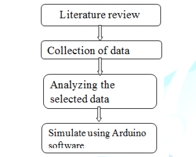
Figure 1: Methodology of the project.
System
development Tools: The system
consists of hardware and software. System development tools are: - motor pump,
LCD, LED, relay, Arduino uno, moisture sensor, transistor, power supply,
battery and resistor.
Hardware
requirement list: The hardware
part involves Arduino Uno R3 microcontroller, motor pump, sensors, Relay and
power supply.
Software
requirement list: The software
part is the Arduino Board is programmed using the Arduino IDE software used to
interface hardware and proteus 8 professional. The Arduino Based Automatic
model atomization the agricultural sector for the development of agriculture
will be focused in the following steps:
·
Complete layout
of the whole setup will be drawn inform of a block diagram.
·
Sensor will
first sense the condition and give its output to the Arduino microcontroller
& displayed on the LCD.
·
The soil
condition is checked by moisture sensor, depending upon the soil condition
& water level, water pump motor is turned on or off.
Significance
of the project
The increasing world population has
led to exponential increase in food demand. This event has necessitated the
need for more land to be cultivated. Due to change of weather patterns brought
about by global warming, irrigation remains as the only reliable method of
crops production.
The systems helps in saving water
and thus more land can be brought under irrigation. Crops grown under
controlled conditions tend to be healthier and thus give more yields.
Project
organization
This project report is organized
into five chapters:
• Chapter
one gives the introduction to the project, the project objectives and the
scope.
• Chapter
Two is the literature review which describes the system and the components used
in the design.
• Chapter
Three gives a complete technical aspect of the design.
• Chapter
Four analyses and discusses the project.
• Chapter
Five gives the conclusion of the whole project, if the objective and scope of
the project were achieved. This chapter also includes appendices and the
references used.
Limitation
of the Project
Some of the major limitation may be
1. Single moisture sensor only covers
the small area of fields.
2. Atmospheric moisture contents
also brought some fluctuation in the measure value of soil moisture content.
3. Some chemical reaction erode the
sensitivity and physical structure of sensor.
Literature
Review
Sensors
A sensor is a device that detects
and measures a physical quantity from the environment and converts it into an
electronic signal. The physical quantity could be moisture, temperature,
motion, light or any other physical phenomenon. Examples of sensors include:
oxygen sensors, temperature sensors, infra-red sensors, humidly sensors, soil
moisture sensors and motion detection sensors. The output of the sensors is
usually charge, current or voltage [4].
Soil
Moisture Sensors
A soil moisture sensor is a device
that measures the volumetric water content (VWC) of soil. Mathematically VWC,
θ, is given as follows;
Θ=Vw/VT
Equation 2-1:
mathematical representation of VWC.
Where: Vw is the water volume and
VT is the total volume (soil volume + water volume).
Soil moisture sensors are
classified according to how they measure the soil moisture content.
Types
of soil moisture sensors:
Electrical
resistance blocks Sensors:
These sensors are made up of two
electrodes made from a porous substance like sand ceramic mixture or gypsum.
The two electrodes are imbedded in the soil during installation [4]. Moisture
is allowed to move freely in and out of the sensors electrodes as the soil
becomes moist or dries up. The resistance of the electrodes to the flow current
is correlated with moisture content. To measure this resistance the electrodes
are biased (energized) with a dc voltage and the current flowing through them
measured. Applying Ohms law;
R=V/I
Where: R is resistance (Unknown) (Ω)
V is biasing voltage (3.3V to 5.0V)
I is the current flowing through the
electrodes (Amps)
When the moisture content in the
soil is high more current will be allowed to flow thus indicating low
resistance. On the other hand for dry soils the sensor will indicate higher
resistance portrayed by the low current reading. This type of sensor is cheap
and readily available. Electrical resistance blocks Sensors can also be readily
assembled from home using two metal plates or steel nails. Electrical
resistance blocks Sensors are mostly used in small projects and gardens due to
the following disadvantages;
·
They are badly
affected by soil PH and salinity thus requiring regular maintenance
·
They have low
sensitivity.
·
The electrodes;
especially which provides a constant source of ions; do not dry at the same
rate as the soil surrounding it.
Electrical
conductivity probe sensors: Electrical
conductivity probes employ the same principle as the Electrical resistance
blocks Sensors. The one major difference between the two types of sensors is
that Electrical conductivity probes sensors have their electrodes/probes in
direct contact with the soil [4].
A large volume of water will mean
more ions and thus better electric conduction. Electrical conductivity probes
sensors takes advantage of this phenomenon [4].
The amount of current passing between
the probes is directly proportional to the soil moisture content. Moist soil
allow more current to flow between the probes while drier soils only allow a
little current to flow between the probes. Better conductivity indicates a
lower electrical resistance. Most of the soil moisture sensors currently in the
market especially for small projects are Electrical conductivity probes
sensors. They have the following advantages.
·
They are cheap
·
They are readily
available
·
Easy to
calibrate and install
Dielectric
sensors: Dielectric sensors
measure the soil water content in the soil by measuring the dielectric
permittivity of the soil. A dielectric material is substance that does not
conductor electricity, but supports electrostatic fields efficiently. The volume
of water in the soil influences the dielectric permittivity of soil [4].The
dielectric of water which is 80.4 is greater than other soil constituents.
Therefore change in the amount of water in the soil will directly lead to
change in the soil dielectric permittivity.
Dielectric sensors are classified
into two types namely: Capacitance sensors and Time Domain Reflectometry (TDR)
sensors. These sensors do not measure electrical conductivity while measuring
soil moisture [7].
Capacitance
sensors: Capacitance sensors use
frequency domain reflectometry (FDR).Frequency domain reflectometry is the
measure of signal reflections through a medium across frequency. Capacitance
sensors contain two electrodes which are separated by a dielectric material.
Time
Domain Reflectometry (TDR) sensors: Time
Domain Reflectometry uses the principle of waveguides. The actual content of
water in the soil is measured under this technology and not the water potential
[7]. The TDR device sends signals to the rods inserted in the soil. The time
required for an electromagnetic signal to travel along the wave guide is
measured. The rate at which the send signal returns is used to measure the
water content in the soil. The return rate is dependent on the dielectric
properties of the soil. The signal takes longer time in moisture soils and
shorter time in dry soil. This pulse signal is then converted into soil
moisture measurement [4]. TDR sensors give accurate readings faster and require
very little maintenance. The major disadvantage of TDR sensors is that they
require different calibrations depending on different soil types.
Heat
dissipation sensors: Heat dissipation
sensors measure the soil moisture content by measuring the amount of heat
dissipated from a medium which is of ceramic kind in most cases. The water
contained in the medium spaces is directly proportional to the heat dissipated
from the medium [8]. The less the water contained in the medium the less the
heat dissipated and more heat is dissipated if the water contained in the
medium is high. More heat dissipated leads to lower reading on the sensor and
less heat dissipated leads to higher reading on the sensor.
Tensiometer
Sensors: Tensiometers sensors
measure the soil moisture content in the soil by measuring the moisture
tension/suction in the soil. Tensiometers sensors is made up of two major parts;
a plastic tube which has a ceramic porous medium at its tip and a vacuum gauge
on the opposite end [7].
During installation the ceramic tip
is buried in the soil at the calibrated depth which should be as near as
possible to the plants root area. The vacuum gauge measures the effort the
plants roots have to put to extract water from the soil [4]. This is the
measure of the soil measure tension which is measured in centibars. If the soil
moisture content is low the roots work harder to extract water from the soil.
The reading on the sensor is high. When water is more available in the soil the
roots works less and thus lower reading is indicated on the sensor [8].
YL-69
Moisture Sensor: This is an
Electrical resistance Sensor. This soil moisture sensor reads the moisture
content around it. A current is passed across the electrodes through the soil
and the resistance to the current in the soil determines the soil moisture.
Digital
potentiometer: A potentiometer is
basically a variable resistor. Like analog potentiometers, digital
potentiometers are used to scale or adjust resistance of a circuit. Digital
potentiometers are also known as a digital pot or digipot. Digipots are used
mostly in scaling analog signals to be used in a microcontroller.
Digipot output resistance is
variable based on digital inputs and thus also known as resistive
digital-to-analog converters (RDACs). Some RDACs come with nonvolatile memory
thus provide wiper setting retention after a power ON to OFF cycle. Digipots
are available as integrated circuits (ICs).
On the soil moisture sensor the
digital potentiometer acts as a low resolution digital to analog convertor
(DAC) thus adjusting it varies the sensitivity of the sensor.
LM393
comparator: A compactor is an
electronic device that compares two voltages or currents and gives a digital
signal as the output. It indicates which of the two compared quantities is
large. A comparator has a least two input pins and one output pin. Operational
amplifier operating in open loop configuration and without negative feedback
can be used as a simple comparator.
Sensor
Selection
When deciding on which sensor to
use the following factors should be put into consideration: [4,8].
Price: This is the most important parameter when selecting
any component. The price of the sensor will ultimately affect the price of the
whole system as this is one of the major system modules. Sensor with the most
competitive price should be chosen.
Power: In any electrical system power efficiency is
critical. Moisture sensor will low power consumption should be selected.
Sensors which can be battery powered can be used in areas without electricity
connection.
Technology: Technology used to design sensor dictate the
sensitivity, cost and durability of the sensors. Most low cost sensors have
poor sensitivity, rust and corrode over time. Resistive or conductive sensors
which are affected by soli salinity thus have a short life.
Shape: Long and slender sensors can be used in many
applications than bulky ones.
Durability: Soil moisture sensor which are not affected by soil
salinity, corrode or rust should be selected. Soil moisture sensor probes that
measure conductivity should be avoided, since they will wear out over time.
Accuracy
and Linearity: A quality soil
moisture sensor probe should give an output which is proportional to water
content over the full output range. In addition, the soil moisture sensor probe
should have a good output range to reduce sensitivity to noise.
Voltage
Range: Choose a sensor that
has a big supply voltage range. Powering a sensor with the wrong voltage will
damage the sensor or give inaccurate results.
Sensor
Installation
Sensors orientation and
installation depends on the sensor type, size and shape (flat, node, and rod).
Installation should be guided by the manufacturers installation manual. But in
general the sensor should be installed as close to the root area as possible [4].
On new fields; the SMS should be installed prior to planting crops. The sensor
should be installed at approximately 3 inches deep. For existing fields
trenches are dug at uniform intervals and SMS installed Flat sensor probes are
commonly found in two types and typically use TDT technology. These are the
Exposed wave guides and the Encased wave guides. Both of these sensor types are
installed horizontally [7]. Node probes type soil moisture sensors are usually
installed vertically around the root area. Granular Matrix technology is
typically used in this SMS type.
For rod type probes SMSs; the
probes are installed inclined at 450 to the ground to allow the probes to the
read moisture content from the root zone. TDR technology is typically used in
this class of sensors. SMSs should be installed away from structures, tree
canopy, construction roads and plant debris.
Sensor
Calibration
As is the case of sensors
installation, sensor calibration should also be done in line with the manufacturers
specifications. Different sensors have different calibration procedures.
Development stage of the plants root also determines the SMSs calibration [7].
The soil type and crops water requirements greatly influence the sensors
calibration.
Maintenance
The technology used to design the
sensors determines the regularity of maintenance. Electric resistance and
conductance sensors tend to corrode with time and thus require regular
maintenance and replacement. TDT and TDR sensors are the most stable and
durable thus requiring minimum maintenance.
Microcontroller
A microcontroller consists of
peripherals such as RAM, EEPROM, Timers etc., required to perform some
predefined task [1]. There are different microcontroller types including: 8051,
PIC (Programmable Interface Controller) and AVR. Microcontrollers are used in
digital applications as control units [3]. Some microcontrollers come with
their in-build circuits like Analog to digital convertors or digital to analog
convertors.
Microcontrollers are mostly
programmed using assembly language but in recent years high level languages
like C, C++ PASCAL and java have been used [5]. High level programming of
microcontrollers brings the advantage of not having a different program for
each microcontroller manufacturer. High level programming is also neat, easy to
document and maintain and user friendly.
Types
of Microcontrollers
8051
Microcontroller: These are among
the earlier microcontrollers to be fabricated. Due to superiority in technology
in the newer versions, very few companies still fabricate 8051. Earlier 8051
have 12 clocks per instruction whereas the newer versions have 6 clocks per
instruction. 8051 microcontroller does not have memory bus and ADC. First 8051
microcontroller to be fabricated with Harvard architecture was done in 1980 by
Intel [1].
Programmable
Interface Controller (PIC): Programmable
Interface Controllers are commonly referred to as PIC. PICs are slightly older
than 8051 microcontrollers. PICs are preferred to 8051 because of their small
low pin count devices. PICs perform better and are affordable than 8051 [3].
The Microchip technology fabricated the single chip microcontroller PIC with
Harvard architecture. The only major downside of PIC is its programming part is
very tedious. PICs are hence not recommended for beginners.
AVR:
In 1996, Atmel fabricated this
single chip microcontroller with a modified Harvard Architecture. This chip is
loaded with C- compiler and a free IDE. Like PIC, AVR microcontrollers are
difficult for the beginners to work with. AVR microcontroller has on-chip
boot-loader thus AVR can be programmed easily without any external programmer [3].
AVR controllers has number of I/O ports, timers/counters, interrupts, A/D
converters, USART, I2C interfaces, PWM channels, on-chip analog comparators.[8].
Arduino
Arduino is an open-source
electronics design platform. The Arduino board is specially designed for
programming and prototyping with Atmel microcontrollers [5]. An arduino
interacts with physical world via sensors. Using arduino; electric equipments
can be designed to respond to change in physical elements like temperature,
humidity, heat or even light [5]. This is the automation process. For example,
reading a humidity sensor and turning on and off of an automatic irrigation
system. There several types of arduino boards.
The open-source Arduino environment
allows one to write code and load it onto the Arduino boards memory. The
development environment is written in Java and based on Processing, AVR-GCC,
and other open source software [5]. Similarly, AVR-C code can be added directly
into the Arduino programs if one so wishes [5].
Types
of arduino boards
Legacy
Versions: Arduino legacy versions
include Arduino NG, Diecimila, and the Duemilanove. These arduinos use
ATMEGA168 chips. They require manual selection of either USB or battery
power.[5]. For Arduino NG one is required to hold the rest button on the board
for a few seconds before uploading a program on to it.
Arduino Uno
This is the most common arduino
type. This arduino type uses ATmega328 AVR microcontroller.
ATmega328 is more preferred due to
the following features:
·
Have three 8-bit
bi-directional I/O ports with internal pull-up resistors.
·
1K Bytes EEPROM
·
32K Bytes of
flash memory.
·
2K Bytes of RAM
Arduino
Mega 2560: This is regarded as an
advancement of arduino uno. It has more memory than arduino uno. It has a total
of 54 input pins of which 16 are analog inputs. It has a larger PCB board than
arduino. Overall it is more powerful than arduino uno. This arduino board is
based on ATmega2560 [5].
Arduino
LilyPad: This arduino board is
designed for wearable applications. It is usually sewn on fabric. This board
requires the use of a special FTDI-USB TTL serial programming cable. Arduino
LilyPad is used to design "smart" wearable [5].
Arduino
Mega ADK: This arduino board is
specifically designed to interact with android devices.
Automatic
switching circuits: In electronics
automation many times the designer is confronted by a situation where he/she
has to switch very high voltage equipment on, using a low voltage circuit. For
example using a 5v dc voltage, it is possible to switch on/off a 230v ac
machine [6]. Digital or discrete signals enables as opposed to analog signals
are used. There are a number of components used in electronic switching today.
The
Triac Switching circuit: The Triac is a
two thyristors connected back to back, used for high or medium power control
for both a.c and d.c applications. Either of electrodes A2 and A1 can act as
anode and either is cathode. The device can be triggered by either positive or
negative voltage on the gate with respect to A2. This device is effectively two
thyristors (SCR s) back to back in construction with an external n-region which
is the gate.
Relay
switching circuit: This is an
electromagnetic switch which is activated when a current is applied to it. A
relay uses small currents to switch huge currents. Most relays use principle of
electromagnetism to operate but still other operating principles like solid
state are also used [6]. A contactor is a type of relay which can handle a high
power required to control an electric motor or other loads directly. Solid
state relays have no moving parts and they use semiconductor devices to perform
switching.
A relay is usually an
electromechanical device that is actuated by an electrical current. The current
flowing in one circuit causes the opening or closing of another circuit. Relays
are like remote control switches and are used in many applications because of
their relative simplicity, long life, and proven high reliability. Relays are used
in a wide variety of applications throughout industry, such as in telephone
exchanges, digital computers and automation systems.
Highly sophisticated relays are
utilized to protect electric power systems against trouble and power blackouts
as well as to regulate and control the generation and distribution of power.
Although relays are generally associated with electrical circuitry, there are
many other types such as pneumatic and hydraulic. Input may be electrical and
output directly mechanical, or vice versa.
Resistors
A resistor is a passive
two-terminal electrical component that implements electrical resistance as a
circuit element. Resistor is a component that resists the flow of direct or
alternating electric circuit. Resistors can limit or divide the current, reduce
the voltage, protect an electric circuit, or provide large amounts of heat or
light.
Transistors
A transistor is a semiconductor
device used to amplify and switch electronic signals and electrical power. It
is composed of semiconductor material with at least three terminals for
connection to an external circuit.
System
Design and Description
Components
of Automatic plant watering system
Overall
operation of the project: The automatic
plant watering system has three major parts; humidity sensing part, control
section and the output section. The input to the circuit is applied from the
regulated power supply. The a.c. input i.e. 230v from the mains supply is step
down by the transformer to 5v and is fed to a rectifier.
Working
principle of block Diagram: The power supply
provides power to the Arduino, to the LCD and motor pump. There are two
functional components in this project. They are the moisture sensors and the
motor/water pump. Thus the Arduino Board is programmed using the Arduino IDE
software. The motor can be driven by a 10-12 volt power sources. The moisture
sensor measures the level of moisture in the soil and sends the signal to the
Arduino if watering is required. The motor/water pump supplies water to the
plants until the desired moisture level is reached.
Power
Supply
Power supply is the circuit from
which we get a desired dc voltage to run the other circuits. The voltage we get
from the main line is 230V AC but the other components of our circuit require
5V DC. Hence a step-down transformer is used to get 12V AC which is later
converted to 12V DC using a rectifier.
The output of rectifier still
contains some ripples even though it is a DC signal due to which it is called
as Pulsating DC. To remove the ripples and obtain smoothed DC power filter
circuits are used. Power supplies are designed to convert high voltage AC mains
to a suitable low voltage supply for electronic circuits and other devices. A
power supply can be broken down into a series of blocks, each of which performs
a particular function.
Each of the blocks has its own
function as described below:
1.
Transformer –
steps down high voltage AC mains to low voltage AC.
2.
Rectifier –
converts AC to DC, but the DC output is varying.
3.
Smoothing –
smoothes the DC from varying greatly to a small ripple.
4.
Regulator –
eliminates ripple by setting DC output to a fixed voltage.
Almost all electronics circuit
required DC power supply. DC power supply is the circuit which converts the AC
wave form of power lines to direct voltage of constant amplitude. An ideal
regulated power supply is designed to provide a pre-determined Dc voltage which
is independent of the current drown from the source. These circuits are special
class of feedback amplifiers. All the benefits of TCs are thus obtained:
excellent performance small size, ease of use, low cost, and high reliability
.unregulated power supply has many disadvantages due to which it is not
sufficient for many application.
·
Poor regulation
·
Dc output
voltage varies with the AC input
·
DC output
voltage variation varies with temperature because of semiconductor use to
overcome the above disadvantages.
A 5V-dc power requirement will be
used as input supply to the system. The choice of using a transformer is due to
the low voltage requirement of the system. A transformer of 240/12V in
conjunction with a regulator will be able to provide the needed input 5Vdc.
This means that the RMS value of the transformer secondary is Vrms = 12Vac. The
whole section of the project is powered from a 5V dc power source. To achieve
this 5-volt output, a variable output adapter is used. The adapter takes in
240Vac and gives out from its variable tapped output V dc, 4.5Vdc, 9Vdc, 12Vdc;
the output to the required 5Vdc, the output of the adapter is passed through
the regulator that makes sure that at any point in time, the output it gives is
5V. For convenience, we tap the output of the adapter and hence the input to
the regulator at 6Vdc.
Bridge
Rectifier
A rectifier is a circuit that
converts AC signals to DC. A rectifier circuit is made using diodes. There are
two types of rectifier circuits as Half-wave rectifier and Full-wave rectifier
depending Upon the DC signal generated. Here Full-wave bridge rectifier is used
to generate dc signal.
A bridge rectifier makes use of
four diodes in a bridge arrangement to achieve full-wave rectification. This is
a widely used configuration, both with individual diodes wired as shown and
with single component bridges where the diode bridge is wired internally.
Smoothing:
Smoothing is performed by a large
value electrolytic capacitor connected across the DC supply to act as
reservoir, supplying current to the output when the varying DC voltage from the
rectifier is decreasing. The diagram shows the unsmoothed varying DC and the
smoothed DC. The capacitor charges quickly to the peak of the varying DC and
then discharges as it supplies current to the output.
Working
Principle: First the system starts
and select humidity mode then,
·
If the moisture
value less than the desired value, the motor will pump water.
·
If the moisture
value greater than the desired value, the motor will stop pumping water.
Hardware
design
Control
unit
ATMega328
microcontroller on arduino platform: Arduino
uno is the most common arduino type. This arduino type uses ATmega328 AVR
microcontroller.
The Arduino has several different
kinds of pins, each of which is labeled on the board and used for different
functions.
GND: short for Ground. This ground pin on the Arduino
can be used to ground our circuit.
5V&3.3V: the 5v pin supplies
5volts of power and the 3.3v pin supplies 3.3 volts of power.
Analog: The area of pins under the Analog in label (A0
through A5 on the UNO) is analog in pins. These pins can read the signal form
analog sensors (like a temperature sensor) and convert it into a digital value
that we can read.
Digital: Across from the analog pins are the digital pins (0
through 13 on the UNO). These pins can be used for both digital input (like
telling if button is pushed) and digital output (like powering an LED).
PWM: Some of the digital pins (3, 5, 6,9,10 and 11 on
the UNO). These pins act as normal digital pins, but can also be used for
something called Pulse-Width Modulation (PWM). These pins as being able to
simulate analog output (like fading an LED in and out). PWM signal is needed
for the buzzer to generate sound.
AREF: Stand for Analog Reference. Most of the time we can
leave this pin alone. It is sometimes used to set an external reference voltage
(between 0 and 5 volts) as the upper limit for the analog input pins.
TX
RX LEDs: TX is short for
transmit, RX short for receive. These marking appear quite a bit in electronics
to indicate the pins responsible for serial communication. In our case, there
are two places on the Arduino UNO where TX and RX appear-once by digital pins 0
and 1, and a second time next to the TX and RX indicator LEDs. These LEDs will
give as some nice visual indication s whenever or Arduino is receiving or
transmitting data (like when we are loading a new program on to the board).
ATMega328 microcontroller on
arduino platform was selected the control unit of the microcontroller. Arduino
Uno was selected from the expansive arduino family. Arduino Uno has a total of
20 inputs pins of which 14 are digital and 6 are analog inputs. The digital
pins can be used as either inputs or outputs and also 6 of the 14 pins can be
utilized as PMW. The board has a 16 MHz ceramic resonator, a USB connection and
a power jack.
In the design of the system analog
pins were selected as the arduino input and digital pin was selected as the
arduino output pins.
The pins on the arduino were
selected as shown below.
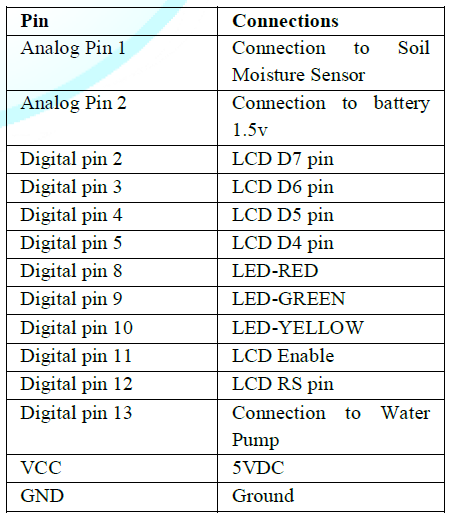
Table 1: Selected pins on Arduino.
Sensing
Unit
YL-69
soil moisture sensor connection to arduino
YL-69 soil moisture sensor was
interfaced to the arduino through a digital a PCB drive. The PCB drive has a
digital potentiometer and a LM393 comparator. The LM393 comparator is used to
compare the voltages across the sensor probes and the set Vcc voltage. The dig
pot is used to alter the sensitivity of the sensor when connected in digital
mode.
Light
Emitting Diode (LED)
A light-emitting diode (LED) is a
semiconductor light source which is used as indicator lamps in many devices and
is increasingly used for other lighting purposes. The color of the light
(corresponding to the energy of the photon) which is determined by the energy
gap of the semiconductor pattern. LEDs are cheap and faster switching.
This stage of the system consist
light emitting diodes (LEDs) that display when executing the operation. Each
phase consists of three patterns of LEDs.
Principle
operation of light emitting diode
Light emitting diode (LED) is a
semiconductor device that operates in forward bias. It consists of two pins,
the long pin which is positive and the short one which is negative.
Benefits
of LED
·
Low power
requirement: most types can be operated with battery power supplies.
·
High efficiency
Long life: when properly installed,
an LED function for decades.
The three LEDs were connected to
the microcontroller
Water
pump connection to the Arduino: The
water pump is used to artificially supply water for a particular task. It can
be electronically controlled by interfacing it to a microcontroller. It can be
triggered ON/OFF by sending signals as required. The process of artificially
supplying water is known as pumping.
To implement the final bit of the
automated irrigation system an electric motor (240VAC) was selected as the
water pump. The first two units of the system i.e. sensing unit and the control
unit (microcontroller) are powered by 12VDC. To interface the two units a 12VDC
relay was used as the isolation unit. The microcontroller was connected to the
relay via an NPN transistor (2N2222). To protect the transistor; while turning
it on, a resistor was used. The resistor limits the current flowing through the
transistor.
Working
Principles of RELAY
All relays contain a sensing unit,
the electric coil, which is powered by AC or DC current. When the applied
current or voltage exceeds a threshold value, the coil activates the armature,
which operates either to close the open contacts or to open the closed
contacts. When a power is supplied to the coil, it generates a magnetic force
that actuates the switch mechanism. The magnetic force is, in effect, relaying
the action from one circuit to another. The first circuit is called the control
circuit.
There are three basic functions of
a relay: On/Off Control, Limit Control and Logic Operation.
·
On/Off Control:
Example: Air conditioning control, used to limit and control a “high power
“load, such as a compressor
·
Limit Control:
Example: Motor Speed Control, used to disconnect a motor if it runs slower or
faster than the desired speed
·
Logic Operation:
Example: Test Equipment, used to connect the instrument to a number of testing
points on the device under test.
To protect the microcontroller from
back e.m.f during switching a diode was connected across the relay.
Liquid
Crystal Display (LCD)
Liquid Crystal Display (LCD) screen
is an electronic display module. An LCD has a wide range of applications in
electronics. The most basic and commonly used LCD in circuits is the 16x2
display. LCDs are commonly preferred in display because they are cheap, easy to
program and can display a wide range of characters and animations.
A 16x2 LCD have two display lines
each capable of displaying 16 characters. This LCD has Command and Data
registers. The command register stores command instructions given to the LCD
while the Data register stores the data to be displayed by the LCD.
The voltage needed is preferable
2-20 V A.C. The voltage threshold for watch type LCD display is 1to 2V. It is
a16 pin device with 16*2 displays. LCD used to display the state of the motor
and the value of relative humidity. When using 8-bit configuration all 8 data
pins (DB0-DB7) are used while only 4 data pins (DB4- DB7) are used in a 4-bit
configuration.
Over
all circuit of Automatic plant watering system
Working
Principle: An automatic plant
watering system using microcontroller ATMEGA328P is programmed such that it
gives the interrupt signals to the motor via the relay.
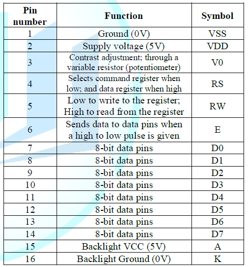
Table 2: LCD Pin configuration.
Soil sensor is connected to the
Arduino board which senses the moisture content present in the soil. Whenever
there is a change in the moisture content of the soil, the sensor senses the
change, giving signal to the microcontroller so that the pump (motor) can be
activated. This concept can be used for automatic plant watering system.
The circuit Diagram works as a
sensor the POT meter or variable resistance measures the moisture level
depending on the amount of water in soil. When the amount of water in the soil
high the conductivity is high and resistivity low vice versa. Depending on this
way the moisture sensor measures the amount of Relative Humidity (RH) in the
soil. The output of POT connects to analog input pin of Arduino Uno.
Results
Analysis and Discussions
ATMEGA 328P micro controller is
the brain of the project which initiates the Relay and LED signal at a
junction. The LEDs are automatically on and off by making the corresponding
port pin of the microcontroller high. So the sequence of the lights determines
the moisture level in the soil.
An automatic plant watering
system using microcontroller ATMEGA328P is programmed such that it gives the
interrupt signals to the motor via the relay. Soil sensor is connected to the
Arduino board which senses the moisture content present in the soil. Whenever
there is a change in the moisture content of the soil, the sensor senses the
change, giving signal to the microcontroller so that the pump (motor) can be
activated. This concept can be used for automatic plant watering system.
The circuit Diagram works as a
sensor the POT meter or variable resistance measures the moisture level
depending on the amount of water in soil. When the amount of water in the soil
high the conductivity is high and resistivity low vice versa. Depending on this
way the moisture sensor measures the amount of Relative Humidity (RH) in the
soil. The output of POT connects to analog input pin of Arduino Uno. If the soil
or plant needs the water, POT sends the signals to Arduino Uno R3 then the
relay become energized. When the relay energized the motor pump start to pump
water to plant until the required moisture level is reached. The three LED
indicates that RH ranges, RED LED indicates high range of RH, GREEN LED
indicates that suitable RH range and YELLOW LED shows that low ranges of RH
values. The LCD display RH values in the soil and the motor pump state or
condition. There are three results that the system implements.
Result
1:
This is the normal condition
meaning the soil moisture is at suitable to the plant. In this condition the
motor pumper off and yellow and Green LED indicates this condition. The RH
range for this condition is that greater than 70.
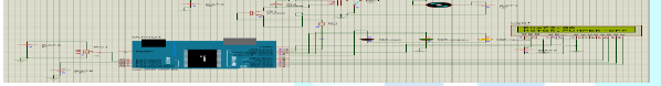
Figure 4: First condition of simulation results.
Result
2:
This is the condition to which
pumping activity takes places, meaning the soil moisture is low or the
temperature is above the desired point.so the plant needs water. In this
condition the motor pump on the water pump until the desired point reached.
Green LED indicates this condition. The RH range for this condition
is than 40-69.
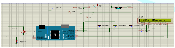
Figure 4.2: Second Condition of simulation result
Result
3:
This condition is problem
indicator by Red LED. Even if the moisture sensor sends a signal to arduino to
pump water but there is no response to signal, in this time the temperature
rises above the desired ranges. The Rh range for this condition is that less
than 40.

Figure 4.3: Third Condition of simulation result.
Discussion
Now a days, farmers couldnt water
their agriculture fields, its because they have no enough knowledge about when
the power is available so that they can pump water .Even after they need to
wait until the field is sufficiently watered, which makes them to dont doing
other activities. So I represent this work to minimize their sufferings.
Conclusion
A system to monitor moisture
levels in the soil was designed. The system was used to switch on/off the
watering system/pump according to set soil moisture levels. The moisture
content of the soil is continuously measured by the sensor. Its value and the
status of motor i.e. ON or OFF condition of motor is displayed continuously on
the LCD. If there is a enough moisture in the soil i.e. there is no need to
irrigate the field then the motor is not switched on but if the moisture
content is very less i.e. there is a need of irrigation then the motor is
switched on automatically and after the field attains the required moisture content,
then the motor is switched off automatically. The control unit the prototype
was implemented using a microcontroller on arduino platform while the sensing
bit was implemented using a SMS YL-69. Three LEDs and an LCD were used to
implement the display of the motor pump state or condition. To switch between
the control and the irrigation systems a relay switching circuit was used.
Recommendation
The project enhanced in way that
controlling automatically the signals depending on relative humidity using
moisture sensors. Water pump motor automatic turn off when RH range value at
high level because RH value and soil moisture directly relation which helps in
power consumption saving. Farther work needed to aware and inform people about
the system. This can be done through Data transfer between the microcontroller
and computer can also be done through telephone network, data call activated
SIM this technique allows the operator to gather the recorded data from a far
end to his home computer or phone without going site and also used to GSM
technology for fault indication.
References
1.
Massimo Banzi. Getting started
with Arduino (2011) Second Edition, OReilly Media, Inc,
2.
Francis Z. Karina, Alex Wambua
Mwaniki. irrigation agriculture in Kenya, Nairobi, Kenya, 2011
3.
Allan Trevennor, Practical AVR
Microcontrollers (2012) New York , USA, Springer Science + Business Media.
4.
Clemmens AJ. Feedback Control for
Surface Irrigation Management (1990) ASAE Publication 4: 90.
5.
www.arduino.cc
6.
Songle relay Datasheet
7.
Soil moisture sensor datasheet
8.
Dunn WC. Introduction to
Instrumentation Sensors, and Process Control (2005) British Library
Cataloguing.
9.
General Purpose Transistors NPN
Silicon (KSP2222A) datasheet
10. http://www.vision2030.go.ke/
11. Greenfield
J. Digital Design using Integrated Circuits (2000).
12. Mazidi
MA, Mazidi JG, Mckinlay RD. The 8051 microcontroller and Embedded Systemb prentice
hall (2006) 3: 2.
13. www.engineersgarage.com

