Introduction
With new generation of fission reactors at physical
reduction size to and smaller footprint that is known as Nuclear Micro
Reactor (NMR), a new door has been opened up for future
space transportation and surface power applications [1]. As we have learned
from undergraduate nuclear engineering class most of Generation Three (GEN-III)
either in form of Light Water
Reactor (LWR) or Pressurized Water
Reactor (PWR) do need to have access to fresh water for
their cooling process, although historically heat pipes system were suggested
and used for cooling core as safety system or either as first or secondary loop
cooling system. For example, mercury heat pipe for Liquid Metal Fast
Breeder Reactor (LMFBR) (i.e. Clinch River Project
under Westinghouse Research and Development program around 1970s time frame)
was implemented as safety cooling system by the first author of this article
[2,3].
One of the aspects of heat pipe application and its
integration in Generation Four (GEN-IV) type reactor as means of heat transfer
system was suggested by Zohuri et al. was for two type of high temperature
reactors such as a Molten Salt Reactor (MSR) and a Fluoride-salt-cooled High-temperature
Reactor (FHR) and it is published in Nuclear Technology journal as a critical
review article, just recently [4]. The Generation IV (GEN IV)
nuclear reactor design and the technology is known as nuclear micro reactors
that are currently under development by many nuclear manufacturer and the
advantages of nuclear micro reactor applications as sources of renewable
energy, their use in military applications and department of defense requirements.
The nuclear industry’s trend toward the design of small and micro reactors for
remote areas with no access to fresh water continuously is investigated by
their engineers and scientists as well. Nuclear Micro Reactor (NMR) safety,
security issues, and cost concerns even for space journey are also explored [1].
One important edge and niche for nuclear energy as
we stated in is the demand for power production at remote locations far away
from reach to a reliable electrical grid. Nuclear power energy has excellent
potential applications at overseas strategic defense locations, theaters of the
remote battlefield, providing power to remote communities, as well as emergency
locations for tribe’s way away from any general population and communities. The
mobility of these types of reactors is another advantage of NMRs. With proper
safeguards, a 1 to 10 Mega-Watt electric (MWe) output, a mobile reactor system
could provide robust, self-contained, and long-term power in any environment.
The integration of an Nuclear Air
Combined Cycle (NACC), not only makes these reactors
to be more efficient from Total Cost of
Ownership (TCO), there would be no need for any external
means of cooling media such as fresh water in respect to “traditional” reactors
of Generation Three or GEN-III [5,6]. Heat pipe-cooled fast-spectrum nuclear
reactors have been identified as a candidate for these applications. Heat pipe
reactors, using alkali metal heat pipes, are perfectly suited for mobile
applications because their nature is inherently simpler, smaller, and more
reliable than “traditional” nuclear power plants.
Reactors come in a range of sizes. The size fits a
variety of applications as shown in Figure
1. Los Alamos
National Laboratory (LANL) has traditionally designed
reactors for applications in the 1 to 200 kilowatt electric (kWe) range as
shown in the first two columns in Figure 1. Most of LANL’s designs have been
for space applications for the National
Aeronautics and Space Administration (NASA) Almost
all of these reactor designs are based on a small highly reflected fast reactor
concept that uses heat pipes as the means of heat removal from the reactor
core. This is an ideal technology for space where reliability and simplicity
are key requirements [7].
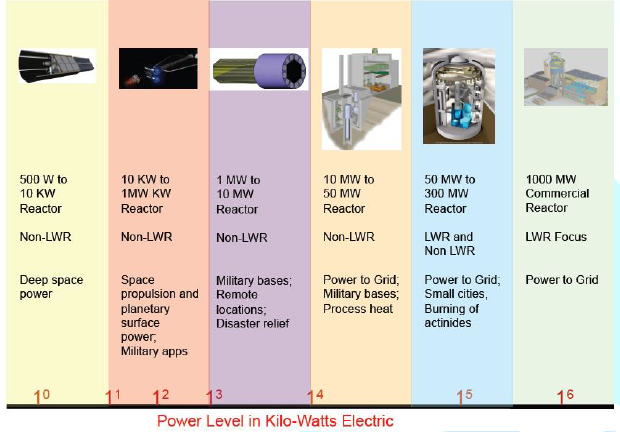
Figure1:Sizes range of reactor applications.
(Courtesy of Las Alamos National
Laboratory)
LANL performed a study to examine the issues of
scaling heat pipe reactor technology to the low MWe range (shown in the third
column of Figure 1.) The low MWe range is an area that was examined in the
1950s through 1970s by the U.S. Army for power at remote locations such as the
Arctic, Antarctica and the Panama Canal. Power at remote locations removed from
a reliable electrical grid is a potential future niche for nuclear energy.
Remote locations include strategic defense locations (such as pacific island bases),
theaters of battle, remote communities (such as northern Alaska), and emergency
locations (e.g., earthquake relief). This was, in part, the goal of the Army
Nuclear Power Program that ran from 1954 through 1977 [7].
An important key technology for Heat pipes driven
nuclear reactors is that the HPs are used as a first loop heat exchanger to
cool the core of reactor. Reactors that are situated in a remote area with
augmented heat pipes as part of their cooling system are perfect for such an
application and they have characteristics such as self-regulation and high
reliability. A heat pipe transfers heat between two bodies with
no temperature change from end to end (isothermally.) A schematic of a heat
pipe is shown in Figure 2. The heat
pipe makes use of the phase change of the fluid as it moves from boiling at one
end to condensation at the other end. This ability makes heat pipes an ideal
means to extract thermal power from a nuclear reactor [7].
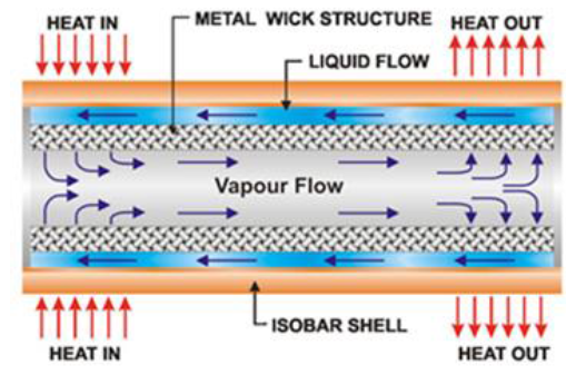
Figure2:The main regions of the heat pipe.
(Courtesy of www.acrolab.com)
Fundamental
of Heat Pipe
A Heat pipe is a two phase heat transfer device with
a very high effective thermal conductivity. It is a vacuum tight device
consisting of an envelope, a working fluid, and a wick structure. As shown in Figure 3, the heat input vaporizes the
liquid working fluid inside the wick in the evaporator section. The saturated
vapor, carrying the latent heat of vaporization, flows towards the colder
condenser section. In the condenser, the vapor condenses and gives up its
latent heat. The condensed liquid returns to the evaporator through the wick
structure by capillary action. The phase change processes and two- phase flow
circulation continue as long as the temperature gradient between the evaporator
and condenser is maintained.
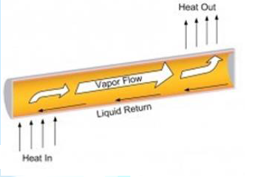
Figure3:A simple physical configuration of heat pipe cut-away [2].
Heat pipes function by absorbing heat at the
evaporator end of the cylinder, boiling and converting the fluid to vapor. The
vapor travels to the condenser end, rejects the heat, and condenses to liquid.
The condensed liquid flows back to the evaporator, aided by gravity. This phase
change cycle continues as long as there is heat (i.e. warm outside air) at the
evaporator end of the heat pipe. This process occurs passively and there is no
external electrical energy required.
At the hot interface of a heat pipe a liquid in
contact with a thermally conductive solid surface turns into a vapor by
absorbing heat from that surface. The vapor then travels along the heat pipe to
the cold interface and condenses back into a liquid-releasing the latent heat.
The liquid then returns to the hot interface through capillary action,
centrifugal force, or gravity, and the cycle repeats. Due to the very high heat
transfer coefficients for boiling and condensation, heat pipes are highly
effective thermal conductors. The effective thermal conductivity varies with
heat pipe length and can approach 100 kW/(m•K) for long heat pipes, in
comparison with approximately 0.4 kW/(m•K) for copper.
Heat pipes
employ evaporative cooling to transfer thermal energy from one point to another
by the evaporation and condensation of a working fluid or coolant. Heat pipes
rely on a temperature difference between the ends of the pipe and cannot lower
temperatures at either end below the ambient temperature (hence they tend to
equalize the temperature within the pipe) (Figure
4).
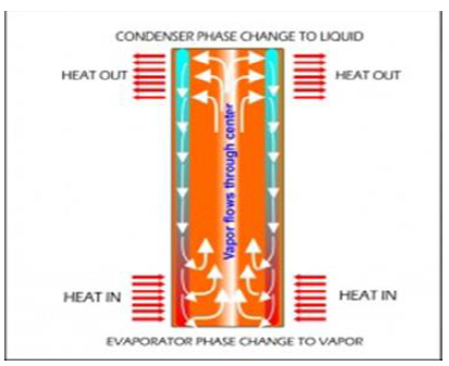
Figure4:Internal schematic heat pipe structure [2].
Heat pipes have an envelope, a wick, and a working
fluid. Heat pipes are designed for very long term operation with no
maintenance, so the heat pipe wall and wick must be compatible with the working
fluid. Some material/working fluids pairs that appear to be compatible are not.
For example, water in an aluminum envelope will develop large amounts of
non-condensable gas over a few hours or days, preventing normal operation of
the heat pipe.
Heat pipes are manufactured in two types in general,
as shown in Figure 5 and Figure 6, depending on their
applications as: [8]
1. Constant Heat Pipe (CHP).
2. Variable Heat Pipe (VHP).
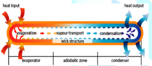
Figure5:A Simple Constant Heat Pipe (CHP) configuration.
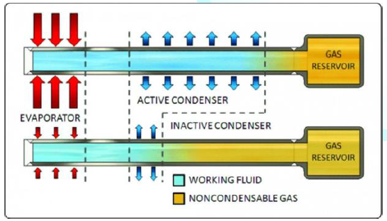
Figure 6: A Simple Variable Heat Pipe (VHP) configuration.
Furthermore, In addition to standard, Constant
Conductance Heat Pipes (CCHPs), there are a number of other
types of heat pipes, including:
•
Vapor chambers
(planar heat pipes), which are used for heat flux transformation, and
isothermalization of surfaces
•
Variable Conductance Heat Pipes (VCHPs),
which use a Non-Condensable Gas (NCG) to change the heat pipe effective thermal
conductivity as power or the heat sink conditions change
•
Pressure Controlled Heat Pipes (PCHPs),
which are a VCHP where the volume of the reservoir, or the NCG mass can be
changed, to give more precise temperature control
•
Diode heat pipes, which have a high
thermal conductivity in the forward direction, and low thermal conductivity in
the reverse direction
•
Thermosyphons, which are heat pipes
where the liquid is returned to the evaporator by gravitational forces
•
Rotating heat pipes, where the liquid is
returned to the evaporator by centrifugal forces
Fundamental
Operation of Heat Pipe and Thermosyphon Process
The heat pipe shown in Figure 2 is essentially a
constant temperature, heat transfer device. It consists of a closed container
in which vaporization and condensation of a fluid takes place. The choice of a
fluid depends on the temperature range in which the heat pipe will be used.
Heat is applied to one end of the heat pipe (evaporator), which raises the
local temperature leading to evaporation of the working fluid.
Note: Thermosiphon (alternately.
thermosyphon) refers to a method of passive heat exchange based on natural
convection which circulates liquid without the necessity of a mechanical pump. Because
of the saturation conditions this temperature difference results in a
difference in vapor pressure, which in turn causes vapor to flow from the
heated section to the cold section of the pipe (condenser). Wicking material is
used in regions to facilitate the path of the vapor to the pipe. Typically, a
good wicking material maximizes the movement of the fluid, has uniform
porosity, has very small pores such that the wick can generate a large
capillary pressure, is resistant to degradation by temperature, and does not
react or degrade chemically with the working fluid. Heat pipes can have a
number of different geometric configurations. These configurations include
cylindrical, spherical, square, or any other geometry such that the inner
volume of the heat pipe forms a channel from the evaporator section to the
condenser section. Metals used to fabricate the heat pipes should be compatible
with the working fluid as well as with the external media in contact with the
evaporator and the condenser. The outermost shell of the heat pipe is referred
to as the container. The container encloses the functioning parts of the heat
pipe and provides structural rigidity.
The liquid flow takes place in a porous material
usually referred to as wick. The interior space of the heat pipe is called the
vapor core, which provides passage for the vapor flow. Heat pipes have been
used extensively in a variety of energy storage systems such as chemical
reactors and spacecraft temperature equalization. Heat pipes are well suited to
thermal storage systems, particularly in the roles of heat delivery and
removal, because of their highly effective thermal conductivity and passive operation.
Heat
Pipe Operational Limits
As with any other system, the performance and
operation of heat pipes are limited by various parameters. Physical phenomena
that might limit heat transport in heat pipes include capillary forces, choked
flow, interfacial shear and incipient boiling. The heat transfer limitations
depend on the size and shape of the pipe, working fluid, wick parameters, and
operating temperature. The lowest limit among these constraints defines the
maximum heat transport limitation of a heat pipe at a given temperature. The
operation limits of a heat pipe as illustrated in Figure 7, in the order of increasing power throughput and
temperature, are the viscous, sonic, wicking or capillary, entrainment,
boiling, and heat rejection. The latter is dictated by the length of the
condenser section, surface emissivity and available area for heat rejection in
the radiators for space nuclear reactor power systems [8].

Figure7:Operation limits of a heat pipe
In the design of heat pipes, consideration must be
given not only to the internal structure and fluid dynamics of the pipe but
also to the external conditions imposed upon it. By fully operational steady
characteristics of heat pipe up to now, we have assumed a steady-state heat pipe,
with heat being added to and removed from the heat pipe at a constant rate.
Under this condition we mean that the heat pipe is relatively isothermal, and
heat is being dissipated over the entire length of the condenser. If the heat
pipe input and output rates are then equal, the heat pipe will be functioning
in the steady-state condition. If an imbalance between the heat input and
output rates, take place, then the temperature of the fully operational heat
pipe will continue to change with time to a level at which the balance between
heat input and output rates is restored [9].
For any heat pipe design and its application certain
criteria have to be met and heat transfer limitations should be considered to
make sure the heat pipe works within its design specification and follows its
normal operation as they are listed as a main summary of these limitations.
Viscous
Limit
The viscous limit dominates at low temperature, near
the melting point of the working fluid. The high liquid pressure losses in the
wick, due to the high viscosity and low permeability, limit liquid flow from
the condenser to the evaporator section. Avoiding this limit requires operating
at a relatively low input power until the heat pipe temperature is high enough
to decrease the liquid viscosity and hence, the pressure losses in the wick.
Sonic
Limit
The sonic limit, also dominant at low temperatures,
should be avoided. The vapor pressure of the working fluid is a good indicator
of reaching this limit [9]. The vapor pressure and physical state of the heat
pipe liquid at ambient temperature, as well as the thermal resistance between
the condenser and the adjacent heat sink has significant influence of the
startup behavior of a heat pipe.
Prior to start up, the temperature of a heat pipe is
equal to the ambient temperature, and its internal pressure is equal to the
vapor pressure of the heat pipe liquid at ambient temperature. Also, depending
on its freezing point, the heat pipe liquid may be in the liquid or the solid
state. The transient behavior and problems of heat pipe startup have been
studied by Cotter [10] and Deverall, et al [11]. Tests results reported by
latter indicates that the transient behavior of a heat pipe depends on the
circumstances mentioned above.
As liquid and vapor move in opposite directions, the
vapor exerts a shearing force on the liquid at the liquid-vapor interface. If
this shear force exceeds the surface tension of the liquid, liquid droplets are
entrained into the vapor flow and are carried towards the condenser section as
it is illustrated in Figure 8. The
magnitude of this shear force depends on the thermo-physical properties of the
vapor and its velocity and if it becomes large enough, it causes dry out of the
evaporator [9].
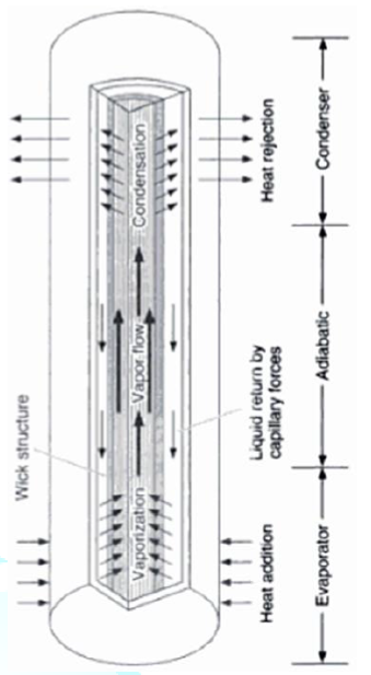
Figure8:Schematic of heat pipe
Entrainment
Limit
The Entrainment Limit at high vapor velocities,
droplets of liquid in the wick are torn from the wick and sent into the vapor,
which results in dry out. An abrupt wick dry out will take place when
entrainment begins and there is a sudden substantial increase in fluid
circulation to the point that the return liquid system cannot accommodate this
flow increase. This limit was identified by Kemme [12] when he discovered the
sound sounds that were made by droplets from media liquid within heat pipe
striking the condenser end of the heat pipe and through the abrupt overheating
of the evaporator.
The entrainment limit also is known as an axial heat
flux, the heat transport rate per unit of vapor space cross-section area. Under
this condition, the fluid velocities increase so as the drag force as the heat
transport rate through the heat pipe increases. The drag force on the heat pipe
liquid is proportional to the liquid surface area in the wick pores, whereas
the resisting surface tension force is proportional to the pore width normal to
the drag force. Consequently, the ratio of the drag force to the surface
tension force is proportional to the pore size and decreases as the pore size
diminishes [9].
The entrainment limit is typically encountered
during a heat pipe startup, when the vapor flow at the evaporator section exit
is chocked (velocity is near sonic). The induced interfacial shear stress at
the surface of the liquid saturated wick, by the vapor counter-current flow
could not only slow down the liquid flow to the evaporator section, but also
break up and entrain tiny liquid droplets back to the condenser. The reduced
replenishing of the wick in the evaporator section with liquid could result in
a local dry out. The entrainment limit could be raised by employing a small
pore size wick and/or increasing the cross-sectional flow area for the vapor in
the heat pipe to lower its velocity at the exit of the evaporator section.
Wicking
Limit
The “wicking limit” or “capillary limit” is the best
understood. This condition is occurring when an applied heat flux causes the
liquid in the wick structure to evaporate faster than it can be supplied by
capillary pumping power of the wick. Once this event takes place the meniscus
at the liquid-vapor interface continues to withdraw and move back into the wick
until all of the liquid has been depleted. This action will result the wick to
become dry and heat pipe container temperature may continue to rise at the
evaporator until a “burnout” condition is reached [13]. The difference in the
capillary pressure across the liquid-vapor interfaces governs the operation of
the heat pipes. This is one of the most important parameters that affect the
performance and operation of a heat pipe. It is usually a major limiting factor
in the working of low-temperature or cryogenic heat pipes [9,14].
The capillary limit is encountered when the
capillary pressure is not sufficient to pump the liquid back to evaporator
causing the dry out of the wick of the evaporator end. The physical structure
of the wick is one of the most important reasons for this limit and the type of
working fluid affects it. Once limit is encountered, any further increase in
heat input may cause serious damage to the heat pipe [9]. The performance and
operational characteristics for a given heat pipe and thermosiphons as a
function of the mean adiabatic or operating temperature and envelop of these
operating limits have been discussed in above (Figure 9).
Any design of heat pipe that falls within operation
envelop of its function (red color) essentially considered as a good design and
will work within specific function of operating temperature that is defined for
that design [1]. Thus, The capillary (or wicking) limit is encountered when the
net capillary pressure head is less than the combined pressure losses of the
liquid flow in the wick and of the counter-current vapor flow in the heat pipe.
The capillary pressure head for circulating the heat pipes working fluid
increases with increasing the liquid surface tension and decreasing radius of
curvature of the liquid-vapor meniscus in the surface pores in the wick, as
illustrated in term of Rc in Figure 9
[8].
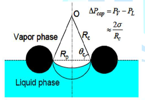
Figure 9:Capillary pumping of the working fluid in heat pipe [2].
Boiling
Limit
A boiling at the inside surface of the heat pipe
wall in the evaporator section is likely when the local liquid superheat
exceeds that for incipient nucleate boiling. The ensuing nucleation and growth
of vapor bubbles block the flow of returning liquid to the evaporator section. In
alkali-metal heat pipes, the boiling limit is typically encountered at high
wall temperatures, beyond those selected for nominal operation [8].
An additional operation limit, often overlooked, is
that of heat rejection in the condenser section. In space reactor power
systems, the condenser section of the radiator heat pipes is cooled by thermal
radiation into outer space. Therefore, the heat removal rate is proportional to
the effective surface emissivity and area in the condenser section and the average
surface temperature to the fourth power. Metallic surfaces
typically have low emissivity, thus are treated with a black coating or paint
to improve heat rejection. This operation limit might be encountered late in
life, due to the accumulation of non-condensable gases, generated [8].
Heat
Pipe Pros and Cons
Heat pipes are tubes that have a capillary wick
inside running the length of the tube, are evacuated and then filled with a
refrigerant as the working fluid and are permanently sealed. The working fluid
is selected to meet the desired temperature conditions and is usually a Class I
refrigerant. Fins are similar to conventional coils-corrugated plate, plain
plate, spiral design. Tube and fin spacing are selected for appropriate
pressure drop at design face velocity. HVAC systems typically use copper heat
pipes with aluminum fins; other materials are available.
Advantages:
•
Passive heat exchange with no moving
parts,
•
Relatively space efficient,
•
The cooling or heating equipment size
can be reduced in some cases,
•
The moisture removal capacity of
existing cooling equipment can be improved,
•
No cross-contamination between air
streams.
Disadvantages:
The use of the
heat pipe
•
Adds to the first cost and to the fan
power to overcome its resistance,
•
Requires that the two air streams be
adjacent to each other,
•
Requires that the air streams must be
relatively clean and may require filtration.
Heat
Pipe Applications
A heat pipe is a passive energy recovery heat
exchanger that has the appearance of a common plate-finned water coil except
the tubes are not interconnected. Additionally, it is divided into two sections
by a sealed partition. Hot air passes through one side (evaporator) and is
cooled while cooler air passes through the other side (condenser). While heat
pipes are sensible heat transfer exchangers, if the air conditions are such
that condensation forms on the fins there can be some latent heat transfer and
improved efficiency (Figure 10).
Application of heat pipe heat exchanger enhancement
can improve system latent capacity. For example, a 1 0F dry bulb
drop in the air entering a cooling coil can increase the latent capacity by
about 3%. Both cooling and reheating energy is saved by the heat pipe's
transfer of heat directly from the entering air to the low-temperature air
leaving the cooling coil. It can also be used to precool or preheat incoming
outdoor air with exhaust air from the conditioned spaces.
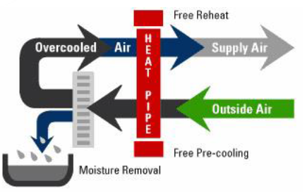
Figure 10: Heat pipe application concept.
The best applications of heat pipe are listed below:
• Where lower relative humidity is an advantage
for comfort or process reasons, the use of a heat pipe can help. A heat pipe
used between the warm air entering the cooling coil and the cool air leaving
the coil transfers sensible heat to the cold exiting air, thereby reducing or
even eliminating the reheat needs. Also, the heat pipe precools the air before
it reaches the cooling coil, increasing the latent capacity and possibly
lowering the system cooling energy use.
• Projects that require a large percentage of
outdoor air and have the exhaust air duct in close proximity to the intake can
increase system efficiency by transferring heat in the exhaust to either
precool or preheat the incoming air.
Moreover, the best possible applications are also
mentioned below as well:
• Use of a dry heat pipe coupled with a heat
pump in humid climate areas.
• Heat pipe heat exchanger enhancement used with
a single-path or dual-path system in a supermarket application.
• Existing buildings where codes require it or
they have "sick building" syndrome and the amount of outdoor air
intake must be increased,
New buildings, where the required amount of ventilation
air causes excess loads or where the desired equipment does not have sufficient
latent capacity.
Other aspects of heat pipes that could be taken
under considerations are:
Technology
Types (Resource)
Hot air is the heat source, flows over the evaporator
side, is cooled, and evaporates the working fluid. Cooler air is the heat sink,
flows over the condenser side, is heated, and condenses the working fluid.
Vapor pressure difference drives the evaporated vapor to the condenser end and
the condensed liquid is wicked back to the evaporator by capillary action.
Performance is affected by the orientation from horizontal. Operating the heat
pipe on a slope with the hot (evaporator) end below horizontal improves the
liquid flow back to the evaporator. Heat pipes can be applied in parallel or
series.
Efficiency
Heat pipes are typically applied with air face
velocities in the 450 to 550 feet per minute range, with 4 to 8 rows deep and
14 fins per inch and have an effectiveness of 45% to 65%. For example, if entering
air at 77 0F is cooled by the heat pipe evaporator to 70 0F
and the air off the cooling coil is reheated from 55 0F to 65 0F
by the condenser section, the effectiveness is 45 % [=(65-55)/(77-55)=45%]. As
the number of rows increases effectiveness but at a declining rate. For
example, doubling the rows of a 48% effective heat pipe increases the
effectiveness to 65%.
Tilt
Based Heat Pipe
Tilt control can be used to:
• Change operation for seasonal changeover,
• Modulate capacity to prevent overheating or
overcooling of supply air,
• Decrease effectiveness to prevent frost
formation at low outdoor air temperatures.
Tilt control (6 maximum) involves pivoting the
exchanger about its base at the center with a temperature-actuated tilt
controller at one end. Face and bypass dampers can also be used.
Nuclear
Power Conversion
In craft the extreme thermal conditions are
encountered. These alkali metal heat pipes transferred heat from the heat
source to a thermionic or thermoelectric converter to generate electricity. Since
the early 1990s, numerous nuclear reactor power systems have been proposed
using heat pipes for transporting heat between the reactor core and the power
conversion system. The first nuclear reactor to produce electricity using heat
pipes was first operated on September 13, 2012 in a demonstration using flattop
fission.
In Nuclear power
plant application, heat pipes can be used as a passive
heat transfer system for performing as overall thermal hydraulic and natural
circulation sub-system in an Inherent Shutdown, Heat Removal System (ISHRS) in
the core (i.e. installed on top of the core doom) of nuclear reactor such as molten
salt or liquid metal fast breeder type reactors, as a secondary fully inherent
shutdown system loop acting like heat exchanger from safety point of view so
the reactor never reaches to its melting point in case of accidental events.
Few concepts of heat pipe driving nuclear power
reactor currently under consideration and envisioned are that, each of the
reactor segments has its own set of heat exchanger. Each segment with its heat
exchanger, reflector and shield is fabricated, assembled and shipped separately
to the reactor site. They are then assembled into the reactor system, and the
secondary sides of the heat exchangers are connected to piping linking them to
the power conversion system. A simple schematic of the reactor, shield and heat
exchanger is shown in Figure 11.
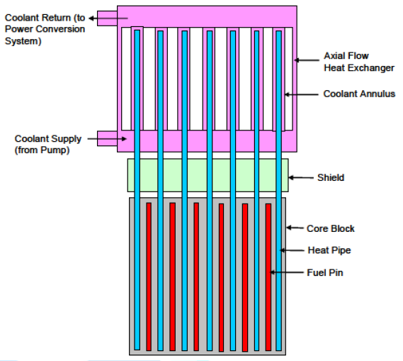
Figure11:Core to heat exchanger schematic [7].
As depicted in above figure, the heat pipes extend
from the reactor core, through the upper shield portion and into the Heat
Exchanger (HX). TH HX has an axial flow configuration. The coolant enters into
a plenum at the bottom, flows up through annuli formed by the heat pipes and
the walls of the heat exchanger, into an upper plenum and exits from a single
pipe there. The advantages of the axial flow heat exchanger are that the length
and annulus area can be selected to produce a desired pressure drop and a
temperature difference between the coolant exit and heat pipe as small as
desired. Also, the core can be easily made into orifice by adjusting the flow
areas [7].
Overall, the fluoride-salt-cooled high-temperature
reactor and some fusion reactors use clean fluoride salts as reactor coolants that
have melting points above 450 0C and generate tritium. The leading
salt coolant option for the FHR is flibe (7Li2BeF4)
containing isotopically-separated lithium-7 to minimize neutron adsorption.
flibe with lithium-6 is proposed as a fusion reactor coolant to maximize
tritium production as a fuel. Some Molten Salt Reactors (MSRs) where the fuel
is dissolved in the coolant also use flibe containing isotopically-separated
lithium-7. In a recent published paper by Zohuri et al. [4], we examine the use
of heat exchangers that contain multiple heat-pipes for transferring (1) heat
from the primary salt coolant to steam or air-Brayton power cycles and (2) FHR
and MSR decay heat from the primary coolant to the environment. Heat pipes can
turn on at preset temperatures and thus reduce the risk of freezing the liquid
salt coolant if the reactor shuts down. Heat pipes can include permeation
barriers to recover tritium that diffuses from the salt coolant into the heat
pipes and thus prevent tritium releases into the power system or environment
for the individual flow annuli. This is especially important for the heat pipes
located at the edges of the blocks, which receive significantly reduced power.
In this published paper [4], a clean flibe salt
coolant is also proposed for high-magnetic-field fusion machines. For fusion,
flibe with lithium-6 is the only salt coolant option because of the requirement
to generate sufficient tritium to fuel the reactor. Tritium is primarily
generated by neutron adsorption in lithium-6. Tritium is also generated in
smaller quantities from fast neutron interactions with lithium-7.
Recent advances in superconductors enable doubling
the magnetic field in fusion reactors [6,7]. In fusion systems, the plasma
power density increases as one over the fourth power of the magnetic field.
Higher magnetic fields can reduce the machine volume by an order of magnitude
but creates major challenges. In a fusion blanket the 14-Mev neutrons slow down
delivering most of the heat from the fusion reactor. With these higher power
densities, it is very difficult to cool solid blankets. As a consequence, it is
proposed to use flibe liquid-salt immersion blankets to adsorb the heat from
the fast neutrons and breed tritium fuel (Figure
12).
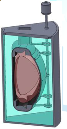
Figure12:Simplified schematic of fusion liquid-salt immersion.
Blanket Source: https://www.wikipedia.org
The blanket has four functions: (1) it slows down
neutrons and converts that energy into heat, (2) the neutrons are used to breed
tritium, (3) the salt acts as the primary radiation shielding to protect the
magnets and (4) high-velocity flibe salt cools the first wall that separates the
fusion plasma from the salt [4].
For fission or fusion applications, these salts will
typically deliver heat through heat exchangers to the power cycle at between
600 and 700 0C. The minimum salt temperature is significantly above
the melting point of flibe (459 0C) for two reasons: (1) flibe near
its melting point is viscous and (2) a reasonable temperature margin is
required to avoid the risk of freezing salt in heat exchangers. The maximum
salt temperature is controlled by availability of economic materials of
construction.
Flibe salt
coolants present two unique challenges for heat exchangers.
First, one must prevent salt freezing by systems that (1) prevent the heat
exchangers from having cold fluids that could freeze the salt or (2) heat
exchanger designs that prevent flibe salt from freezing-the option discussed
herein. Second, one must prevent tritium from diffusing through metal heat
exchangers to the power cycle or the environment. Heat pipes can achieve these
goals [4].
Conclusion
Overall, a heat pipe is a heat-transfer device that
combines the principles of both thermal conductivity and phase transition to
effectively transfer heat between two solid interfaces (Figure 13).
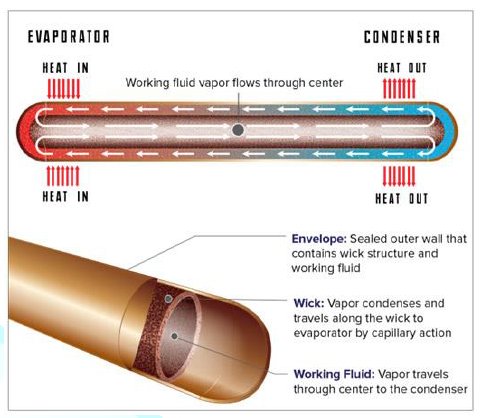
Figure13:Top view depiction of heat pipe infrastructure
Phase-change processes and the two-phase flow circulation
in the HP will continue as long as there is a large enough temperature
difference between the evaporator and condenser sections. The fluid stops
moving if the overall temperature is uniform but starts back up again as soon
as a temperature difference exists. No power source (other than heat) is
needed. In some cases, when the heated section is below the cooled section,
gravity is used to return the liquid to the evaporator. However, a wick is
required when the evaporator is above the condenser on earth. A wick is also
used for liquid return if there is no gravity, such as in NASA’s
micro-gravity applications.
In conclusion, heat pipe reactors could be scaled
into the low to mid 10’s of MW electric with the right choice of fuel and
reactor materials. A recommended power level of about 30 MWe was seen as the
upper end of what could be accomplished with current technology. Other reactor
technologies would make more sense above power levels approaching 100 MWe or
higher. Going forward it makes the most sense to build the first heat pipe
reactors with conventional fuel and materials. The easiest path forward would
be to stay with a uranium oxide fuel and stainless steel.
A possible reactor concept for remote locations is
shown in Figure 14. The reactor
concept is a heat pipe reactor that would be coupled to an open air Brayton
power conversion system. The goal of the concept would be to have a reactor
that could be easily deployed by truck or air transport. A concept for
transport is shown in Figure 15. In
this concept the reactor is flown to a military base and then transported to
site via a semi-truck. Dirt berms are used as partial shielding and the entire
truck is moved into location. The reactor is integrated into the existing power
structure by replacing natural gas driven Brayton power conversion with reactor
driven power conversion [5].
The reactor concept is a heat pipe reactor that would
be coupled to an open air Brayton power conversion system [5]. The goal of the
concept would be to have a reactor that could be easily deployed by truck or
air transport. A concept for transport is shown in Figure 14. In this concept
the reactor is flown to a military base and then transported to site via a
semi-truck. Dirt berms are used as partial shielding and the entire truck is
moved into location. The reactor is integrated into the existing power
structure by replacing natural gas driven Brayton power conversion with reactor
driven power conversion.
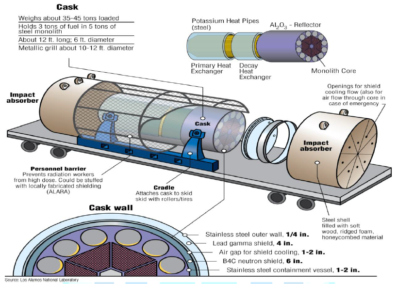
Figure14:Mobile heat pipe reactor in shipping cask [7].
(Courtesy of Las
Alamos National Laboratory)
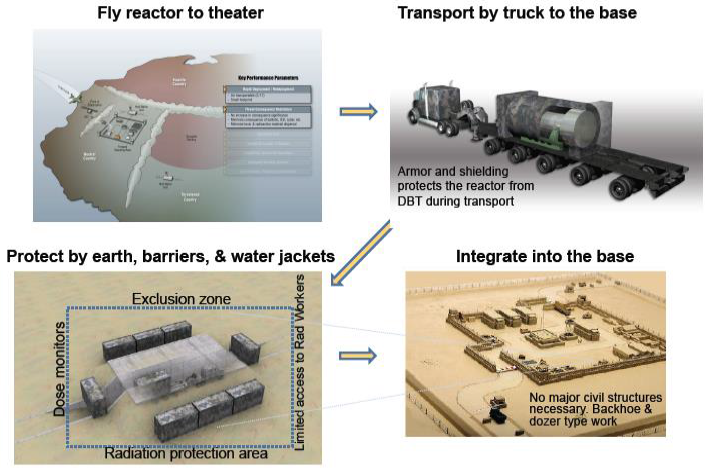
Figure 15:Concept for mobile reactor deployment [7].
(Courtesy of Las Alamos National Laboratory)