Introduction
Epoxy polymer composites with carbon fiber as reinforcement
have an extensive range of applications in many industrial fields as: wind
turbines [1], construction [2], aeronautics [3] and aerospace [4] due to their
favorable strength-to-weight and stiffness-to-weight ratios [5], as well as
their high thermal stability and excellent corrosion resistance [6]. The
performance of fiber-reinforced composites is affected by the properties of the
constituent materials and the load transfer capacity from the matrix to the
reinforcement, this latter feature determined by the interfacial chemical
interactions between fiber and matrix [5]. However, since the present
interactions are poor due to the surface inertness of carbon fiber [7], the
efficiency of composite is limited.
In order to achieve a greater performance, there are
different approaches to modify the surface of the fiber such as polymeric
coating [8], thermal treatment [9], chemical partial oxidation [10], plasma
treatment [11], increase of the surface roughness of carbon fibers [12], or
integration of nanoparticles as fillers into the surface of the reinforcement
[13]. Besides the mentioned approaches, an alternative technique that has
recently emerged is the dispersion of nanofillers into the polymer matrix [5].
Graphene is a candidate to be applied as nanofiller because of its superior
electrical, thermal and mechanical properties [14]. However, the use of
graphene is limited by the lack of an effective method for large-scale
production [15], by its high tendency to agglomerate via Van der Waals
interactions and by its flammability [16,17]. Hence, Graphene Oxide (GO) and
reduced graphene oxide (rGO) are used instead of pristine graphene because both
(of them) contain functional groups such as carboxylic and hydroxyl ones that
facilitate their dispersion in epoxy matrix [18]. Functional groups, can
interact with some molecular structures inside resins composition, and hence,
improving its cohesion. The main difference between GO and rGO is that, while
the former has more functional groups, the latter is more similar to pris- tine
graphene [9]. Several studies have been carried out to determine effects of
applying GO or rGO as nanofiller [19] achieved improvements in flexural
strength by 66 %, flexural modulus by 72 %, and inter laminar shear strength by
25% at 0.3 wt % of GO included in the carbon fiber/epoxy composite [5] employed
electrospraying for the deposition of 0.05 wt % graphene sheets onto carbon
fiber and attained enhancements in the flexural strength and modulus by about
64 % and 85 %, respectively [14].
Dispersed 0.2 wt % rGO to epoxy resin and attained an
increase of glass transition temperature by nearly 11°C, and enhanced its
quasi-static fracture toughness by about 52% [20] added 1.5 vol % GO to the
epoxy matrix and increased its tensile strength from 7 MPa to 13 MPa, the
Youngs modulus improved from 115 MPa to 206 MPa, the maximum applied load from
126 N to 234 N and the elongation at break value jumped from 38 % to 55 %.
Noticeably the number of cycles to failure for the case of GO, directly
spray-coated onto the glass fibers, was about 8 times greater than when the GO
was uniformly dispersed in the resin [21,22] introduced 5 wt % of GO sheets
dispersed in the fiber sizing onto the surface of carbon fibers and achieved
significant enhancement of Interfacial Shear Strength (IFSS), Inter laminar
Shear Strength (ILSS) and tensile properties [23] combined the graphene
nanopowder with a dispersing agent before mixing it with the epoxy resin to
maximize GO dispersion, and the fracture toughness of the carbon fiber/GO/epoxy
resin composite improved an 11.4 % in comparison to conventional composite
without GO.
The synthesis of the catalyzer for the dehydrogenation of
DMAB in ambient temperature, prepared from three monodispersed metallic nano
compound (Pd, Ru, Mi) in GO. (PdRuNi@GO). The GO allows the catalyzer to be
chemically stable, to be a conductor and to have a high catalytic activity,
thus obtaining a great efficiency in TOF for the dehydrogenation catalyzers.
Functionalized GO with thiocarbomide as a Rh-Pt monodispersed NPs support.
(RhPt/TC@GO NPs) for the Kroevenagel condensation of amil aldehyde with
malononitril. Very good catalytic activity for the reactions is obtained. This
can be used in different organic reactions, making them faster. Compound formed
by polyaniline-RGO with Pt (Pt@rGO-PANi) to improve the oxidation reaction of
the alcohol (catalyzer).
Material formed by monodispersed Pt and GO NPs synthesized
with microwave method (Mw-PtNPs@GO). To be used as counter electrode in dye
sensitized solar cells, which produce electricity via photo-electrochemistry.
It changes light energy into electricity with better conversion and efficiency
~7.96%. They have a high electro-catalytic activity. In the present work,
Thermogravimetric Analysis (TGA), X-Ray Photoelectron Spectroscopy (XPS),
Scanning Electron Microscopy (SEM) and tensile and flexural tests are utilized
to study the influence of GO/rGO as reinforcing fillers in mechanical
performance of nano-modified carbon fiber/epoxy resin composites. Carbon Fiber
has demonstrated in the majority of cases of its application as composites
base, a lot of difficulties to reach the close contact with resins used. The
general approach offered by the majority of works [20] never states this fact.
The use of nano-particles is the most promising technique to try to improve its
physical final properties, as can be seen in our experimental results. The
strength remains, or indeed increases lightly, but flexibility is really
improved. The use of these kinds of nano-fillers, due to its three-dimension
capability to, chemically, interact with resin, allows getting closer the
tailor-made approach. Just depending on the chemical constitution of the resin,
different amounts of different nano-fillers, with different chemical groups
available can be used to modify only the desired characteristics of the final
product, without altering its principal mechanical behavior
Materials
Epoxy resins
Epoxy resins are compounds containing several cyclic ethers
with three-atom rings per molecule; the backbones of commercial resins are
usually aliphatic, cycloaliphatic or aromatic. The preparation process of epoxy
resins has a great influence on their functionalities, and treatment with
crosslinking agents produces three-dimensional insoluble thermoset polymers.
These curing agents can be Lewis acids/bases, amines or anhydrides. Three
commercial epoxy resins with their correspondent hardeners denominated as
systems X, Y and Z were employed as the matrix of the composites. To identify
the characterizing of cross-linked resins, thermogravimetric analysis was
utilized; matrix samples were put through thermal decomposition under nitrogen
atmosphere from 25-900°C with a heating rate of 20°C/min. TGA and DTG plots
(Figures 1a and 1b) obtained hint that systems X and Y are quite similar since
their resins are Biphenol Epoxy (BP) and Tetramethyl Biphenyl Epoxy (TMBP),
respectively, and both of them share Methyl Cyclohexane-1.2-Dicarboxylic Anhydride
(MCHDA) as the crosslinking agent [24]. In the particular case of matrix system
Z, it is composed by bisphenol epoxy (DGEBA) and polyoxypropylene diamine
(D230) [25].
The commercial form of the mentioned epoxy resins may
include rheology modifiers; as a re Ma lt of adding these additives, BP, TMBP
and DEGBA viscosity at 20°C are 1950 ± 200, 3240 ± 560 and 9800 ± 1000 cps,
accordingly. The main and immediately noticeable difference between the systems
mentioned is the curing process; whereas resins X and Y require 8 h at 80°C
after sitting for 24 h at room temperature to complete their crosslinking
reaction, resin Z needs 16 h at 60°C after the same precuring conditions.
Figures 1c and 1d present the TGA of the matrix systems performed under air
atmosphere between the same range of temperatures and heating rate as the
method described above. This analysis was carried out to get an insight into
the oxidation behavior of cross-linked resins. Two common thermal degradation
stages can be distinguished in all systems, albeit they manifest different
inflection points and intensities. In the particular case of system Z, there is
an additional stage of weak intensity indicating once again that this matrix is
the most distinctive one.
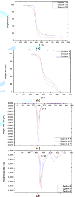
Figure 1: Thermogravimetric analysis of matrix systems: (a) and (c)
under nitrogen atmosphere; (b) and (d) under air atmosphere.
Carbon fiber
Carbon fibers are well known for having a high superficial
inertness; this feature is due to their scarce functional groups, as
illustrated in the Figure 2. The carbon fiber selected as reinforcement of the
composite is characterized by its twill style weave and an area weight of 300
g/cm2.
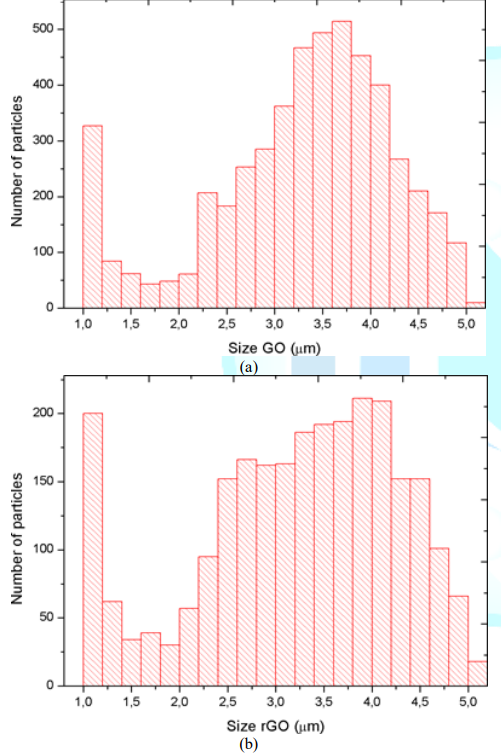
Figure 2: Size distribution of particles of the fillers: (a) GO particles;
(b) rGO particles
GO/rGO
Reinforcing fillers employed to achieve modification of
interfacial interactions between carbon fiber and epoxy resins are 99 % pure
flake-shaped GO/rGO nanopowder. Particle size distribution of GO/rGO is shown
in Figure 3 GO particles are primarily distributed between 3 - 4 µm and a
remarkable quantity of particles is of 1 µm while the number of particles with
other sizes is considerably lower. A similar tendency is present in rGO size
distribution, which has a high scope including sizes of 1 µm and between
2.5-4.5 µm. XPS was the characterization technique employed by the GO/rGO
supplier to identify carbon and oxygen functional groups present on the surface
of the particles. The C1s scan applied involves the electron transition from
carbon-oxygen atoms of different atomic configurations and their shape relies
on their atomic densities. The deconvolution of GO C1s spectra shown in Figure
3a is splitting into 6 peaks: C-C sp2 Monfared Zanjani et al. at 283.9 eV, C-C
in graphitic type at 284.7 eV, C-O single bound at 286.5 eV, C=O double bond at
287.7 eV, O-C=O at 288.9 and the shake-up satellite at 291 eV. The
deconvolution of rGO C1 spectra shown in Figure 3b is split into 4 peaks; C-C
in graphitic type at 284.6 eV, C-O single bond at 286.4 eV, C=O double bond at
287.7 eV and O-C=O at 288.7 eV.
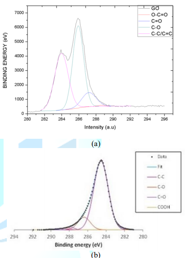
Figure 3: XPS characterization of fillers: (a) GO; (b) rGO
Equipment
CY-500 Sonicator from Optic Ivienm System and T-10 basic
ULTRA-TURRAX from IKA were employed to homogenize the epoxy resin-GO/rGO
systems. An Olympus microscope model BX43 and Advanced Image Analysis and
Nanoparticles Size Identification (APSI) software were utilized to check the
particle size of GO/rGO once dispersed into the matrix. Model JSM-5610 by JEOL
scanning Electron Microscope was employed to obtain high-resolution images of
prepared sample surfaces. Thermogravimetric Analysis was performed with a
TGA/SDTA851e Analyzer from Mettler Toledo, an instrument run by STARe Software.
An electro-mechanical material testing machine fitted with a ball-screw drive
from E series by Zwick Roell group was employed to determine the mechanical
performance of the composites.
Experimental method
Preparation of GO/rGO modified carbon fiber/epoxy composites
To modify the epoxy resins, 0.3 wt % of GO was dispersed in
the matrix by ultrasonication for 30 min achieving a homogeneous system and
then was mixed with the crosslinking agent. The mixture was applied to the
fiber by manual impregnation using the wet lay-up technique. A similar process
was followed to disperse rGO in the resin, but an additional homogenizing
process at a speed of about 20500 rpm with Ultra Turrax was required to get a
nano heterogeneous system before incorporating the crosslinking agent. The
curing conditions of each epoxy resin/hardener systems are specified in the
materials section above and the preparation process is depicted schematically
in the Figure 4, where the homogenizing process refers to ultrasonication plus
Ultra Turrax to disperse rGO, or only the first procedures when incorporating
GO in the matrix.
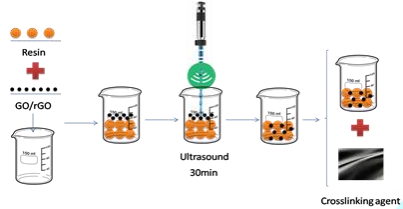
Figure 4: Preparation process scheme.
Determination of mechanical properties of the composites
Tensile and bending tests were performed on the obtained
composites to determine changes in their mechanical properties. Tensile tests
were performed in accordance with specifications designated in ISO 527-1:2012.
Test specimens taken from flat areas of composites had a width of 15 ± 5 mm, an
overall length of 250 mm and a thickness less than or equal to 1 mm. The tests
were conducted at a speed of 2 mm/min. Three-point bending tests were conducted
at a speed of 1 mm/min on specimens which dimensions were 100 × 15 × 2 mm,
according to ISO 14125:1998.
TGA Characterization
Thermogravimetric analysis was applied to characterize raw
carbon fiber, epoxy resins and elaborated composites. Samples of about 10 mg
were placed in aluminum oxide crucibles and then placed on the microbalance of
the analyzer. Thermal degradation experiments were performed from 25° C to
1025°C under air atmosphere at a heating rate of 20°C/min [26-27].
SEM samples preparation
Test samples utilized in tensile tests were analyzed
afterwards with SEM. Specimens were taken as close as possible to the fracture
zone. Clean ruptures were vertically placed in the sample holder while
transverse cracks were horizontally disposed. A thin film of gold was deposited
via 30min sputtering process onto the specimen before inserting the sample
holder into the chamber of the microscope.
Results and Discussion
Mechanical properties
Youngs Modulus, rupture stress and elongation to failure
results are information provided by the tensile test while the flexural stress
result is given by the bending test; variations of mechanical properties due to
the incorporation of reinforcing fillers are collected in Table 1. Many
observations can be pointed out by data interpretation: whereas Youngs Modulus
of X-CF composites experience a great boost by adding GO/rGO. systems with
resins Y and Z not only are barely affected by the incorporation of GO (more
possible molecular interactions due to the presence of more functional groups)
but also undergo a slight reduction of the value of elastic modulus because of
the presence of rGO (less interactions due to functional groups). In regard to
the rupture stress, the values of X-GO/rGO-CF and Y-GO/rGO-CF are over two
times higher than the composite without fillers, but the Z-CF composites show
the same tendency as elastic modulus. As for the elongation to failure, GO/rGO
has a positive impact on X-CF systems, but no significant variations are
detected in Y-CF and Z-CF composites. Bending stress result are also boosted in
X-GO/rGO-CF systems, but the opposite effect is observed in Y-GO/rGO-CF
composites, and in the case of Z-CF ones, only rGO seems to improve this
property.
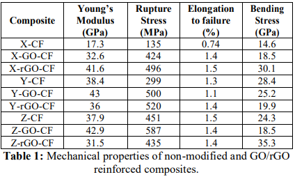
Table 1: Mechanical properties of non-modified and GO/rGO
reinforced composites.
The observations made above suggest that the dispersion of
0.3 wt % of GO in the epoxy resin before the impregnation process certainly
enhances the mechanical properties of the composites, probably due to the
existence of molecular interactions reacted during the dispersion. Adding the
same percentage of rGO in the system generally results in performance
deterioration caused by such factors as poor dispersion of rGO into epoxy,
agglomeration and undesired interaction of GO with a sizing agent [28]. In the
particular case of X-CF composites, rGO also improves the mechanical
performance, which suggests that resin X admits a higher quantity of
nanoparticles than resins Y and Z before reaching the saturation point [19],
where rGO no longer acts as reinforcing filler.
Scanning Electron Microscopy
Fracture surface of samples observed by SEM are shown in
Figure 5. Whereas non- modified composites Figure 5a crack transversely leaving
some fibers damaged and some others untouched, test samples of GO modified
composites Figure 5b break into two halves with a clean rupture. Moreover,
Figure 5b shows interlaminar distribution coinciding with the impregnation
method. Nanoparticles present are shown in Figure 6. GO and rGO modified resins
show a higher density of particles compared to those without reinforcing
fillers. Changes in mechanical properties can be observed in the SEM images,
where non-modified specimens Figure 6 and modified composites without
enhancement of mechanical properties. Figure 6 manifest a bad adhesion (weak or
null interaction) between fibers and epoxy matrix, which causes the occurrence
of the rupture in the interfacial zone. In regard to the composites that
experienced a remarkable boost in their mechanical performance Figure 6, the
epoxy matrix remains attached to the fibers when breaking, what hints which at
a notable adhesion between components.
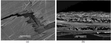
Figure 5: SEM images of fractures caused by applying tensile tests on
Z-CF composites.
With the aim to getting more detailed information about the
effects of reinforced composite with GO/rGO particles, first derivative of the
TGA curves was applied to obtain DTG plots, the results of which are compiled
in Figure 8. The graph allows comparing the variation of the thermal
degradation phases selected, reflecting the level of order that interactions
should create between fiber and resin, thanks to the existence of new
interfaces promoted by GO/rGO presence in the previous dispersion and posterior
cooling process. In Figure 7, peaks are described with the parameters below:
Width (W): horizontal distance from one maximum to the next
one which indicates the variety of interactions ruptured in a degradation
stage. Height (H): also known as intensity is the vertical distance from the
highest maximum to the minimum and expresses the quantity of chemical bonds de-
composed.
Area (A) and Mean Width (MW): represent the relation between
variety and quantity of interactions. Additionally, the Advanced Analysis TGA
(AATGA) software was developed to get a precise analysis of DTG plots. Data
obtained from the program a non-modified composite are gathered in the Table 2
and those GO/rGO composites are collected in Table 3.
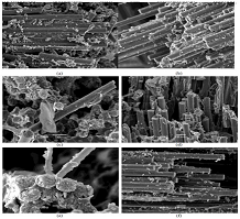
Figure 6: SEM images of composites obtained: (a) Z-CF; (b) Z-GOCF; (c) Z-rGO-CF; (d) X-CF; (e) X- GO-CF; (f) X-rGO-CF
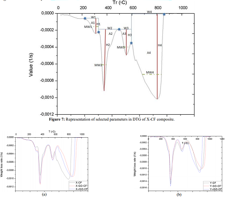
Figure 7: Representation of selected parameters in DTG of X-CF composite.
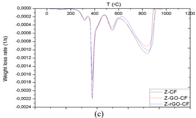
Figure 8: DTG of non-modified and reinforced composites: (a)
X-CF and GO/rGO modified X-CF composites; (b) Y-CF and
GO/rGO modified Y-CF composites; (c) Z-CF and GO/rGO
modified Z-CF composites.
Thermogravimetric Analysis
The first remarkable difference when comparing the tables
above is that the area increases of modified X-CF systems are considerably
greater than to those of modified Y-CF and Z-CF composites. More specifically,
whereas that the mean width of the partial areas have broadened in modified
X-CF and Y-CF composites, no relevant variation is observed in Z-CF composites
with fillers. TGA and DTG curves of the carbon fiber are shown in the Figure 9.
Graphic interpretation indicates that the onset and offset temperatures of main
phase of the thermal degradation are approximates 572 and 874°C, respectively;
moreover, the first derivative of the TGA curve determines 815°C as the
temperature where the maximum rate of mass loss takes place. DTG plots of
matrix systems are shown in Figure 1d with their parameters collected in Table
2. Whereas matrices X and Y present two main degradation stages assigned as partial
areas 2 and 3, an additional phase known as partial area 1 can be identified in
system Z. With regard to DTG curves of obtained composites, four zones that
correspond to different rupture of interactions or chemical bonds of the
structure formed can be distinguished independently of the matrix system
applied:
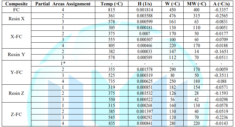
Table 2: DTG data on carbon fiber, epoxy resins and non-modified composites.*although the intensity of the stage in the system is not as significant as
in other composites, slight shoulder can be observed.
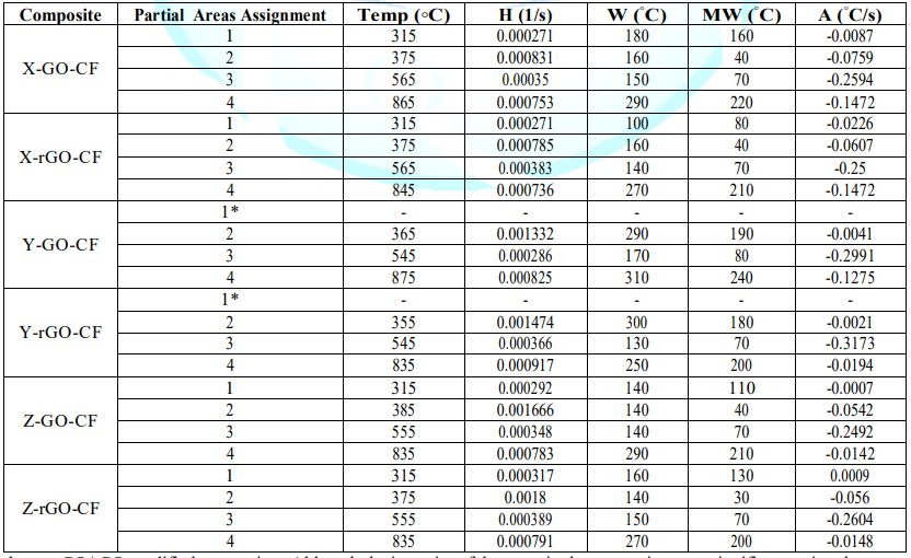
Table 3: DTG data on GO/rGO modified composites. Although the intensity of the stage in the system is not as significant as in other composites, a slight
shoulder can be observed.
•
Partial Area 1, around 250°C: the decomposition intensity is quite weak,
which indicates the presence of a few interactions between matrix and
reinforcement. Whereas this area is noticeable in composites with resins X and
Z, Y-CF, Y-GO/rGO-CF only exhibits a slight shoulder. The incorporation of
fillers also modifies the stage slightly.
•
Partial Area 2, around 380-400°C: the high intensity of this stage
suggests rupture of chemical bonds that belongs to the cross-linked resin,
since this signal is not present in the DTG of carbon fiber. The inclusion of
GO/rGO has no noticeable influence in this decomposition zone.
•
Partial Area 3, around 500°C: the low intensity and the absence of this
signal in carbon fiber suggest that it corresponds to the rupture of
interactions between the residual structure of resin and carbon fiber. Although
a slight shift can be observed in the temperature where maximum rate of weight
loss occurs, this stage is scarcely modified by the presence of GO/rGO.
•
Partial Area 4, around 800°C: this phase corresponds to the thermal
degradation of the carbon fiber. The increase of the offset temperature of the
decomposition indicates existence of intra fiber interactions due to the
presence of fillers.
The use of active fillers (chemical structures that allow
the creation of transversal or lateral interactions with the resin and core
substrate) is more important when high performance materials are to be
obtained. Mechanical performance enhancements are directly linked to the
variations of DTG; a variation of about 11 % in the main area involves an
increase in the properties, in the case where there is no change in the main
area, a secondary area greater than half of a main one experiencing the same
modification it is also translated into a boost of properties. Another pattern
related to bending stress was that modified composites are stiffer than
non-modified ones if there is a decrease greater or equal to 10 % in the main
area; otherwise, the composites are more flexible.
Conclusion
Throughout the article, several facts have been stated
clearly from the experimental results obtained: When working with composite
materials compressed of carbon fiber and epoxy resins, the structure of
hardening agents results in three levels of chemical interactions shown in TGA
and DTG graphs. Fillers effect on the final characteristics of the composite
obtained depends strongly on the level of dispersion obtained. This fact is
also dependent on the size and chemical characteristics of them. The predicted
interactions do not always occur during the cross-linking process. Also DTG
analysis shows the real effect has two possible mechanisms. One of them of weak
character and the other that shows a more intense level of interactions between
matrix, reinforcement and fillers. Although the existence of these interactions
better mechanical behavior cannot always be achieved. When achieved however,
Young Modulus increases enormously which is interesting for specific final
uses. Flexural behavior is affected by the presence of GO or rGO, but due to
the 3D configuration achieved it is difficult to observe a clear influence of
the chemical groups in filler particles.
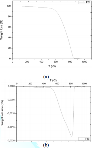
Figure 9: Thermogravimetric analysis of the carbon fiber: (a) TGA
curve; (b) DTG plots.
The role of interfaces is clearly shown in SEM pictures. The
chemical groups of the GO particles do not show a coupling agent effect on the
system. And results show that the interfaces development during the curing
process is one of the most important facts in improving mechanical properties.
The four levels of chemical interactions that exist in the system formed by GO
and rGO when incorporated into a composite material based on carbon fiber and
different epoxy resins. Chemical character of systems X/Y/Z-GO/rGO-CF does not
strongly affect the final interactions formed in the composite material. The
hardening agent has a great influence than the chemical character of rGO and
GO. Improving mechanical properties is just a matter of finding particles with
functional groups designed specifically to the corresponding resin and/or the
substrate used. Carbon fiber has no possibilities of dealing with this approach
due to its chemical inertness. The resonance between the aromatic rings is not
the most appropriate way to try to improve the interactions in a composite
material. The use of larger sized particles faces with the inert interface of
the resin because of its very poor chemical interactions. Therefore, just in
this specific case, and probably for the first time, chemical composition of
the epoxy resins used has been reported. The main idea is to detect with are
the active chemical groups on the resin structure and, from the information
offered by XPS, try to include GO and rGO nanoparticles into the main structure
of the resin, using chemical interactions between chemical groups.
Acknowledgments
The authors would like to show their appreciation to Ruffini
S.L. for then financial support, to Zwick S.L. and Isidoro Soto for permission
to use their testing machine and publish the results and to Mel Composite S.L.
and Torras Suministros Industriales S.L. for providing the material employed in
the present study.
References
1. Kong C, Bang
J and Sugiyama Y. Structural investigation of composite wind turbine blade
considering various load cases and fatigue life (2005) Energy 30:2101-2114.
2.
Triantafillou T and Plevris N. Strengthening of rc beams with
epoxy-bonded fibre- composite materials (1992) Mater Struct 25:201-211.
3. Botelho EC,
Silva RA, Pardini LC and Rezende MC. A review on the development and properties
of continuous fiber/epoxy/aluminum hybrid composites for aircraft structures
(2006) Mater Res 9:247-256.
4. Toldy A,
Szolnoki B and Marosi G. Flame retardancy of fibre-reinforced epoxy resin
composites for aerospace applications (2011) Polymer Degradat Stability
96:371-376.
5. Monfared
Zanjani JS, Okan BS, Menceloglu YZ and Yildiz M. Nano- engineered design and
manufacturing of high-performance epoxy matrix composites with carbon
fiber/selectively integrated graphene as multi-scale reinforcements (2016) RSC
Adv 6:9495-9506.
6. Argon A and
Cohen R. Toughenability of polymers (2003) Polymer 44:6013-6032.
7. Chand S.
Review carbon fibers for composites (2000) J Mater Sci 35:1303-1313.
8. Hughes J.
The carbon fibre/epoxy interfacea review (1991) Comp Sci Technol 41:13-45.
9. Dai Z, Zhang
B, Shi F, Li M, Zhang Z, et al. Determination of the local chemical structure
of graphene oxide and reduced graphene oxide (2010) Adv Mater 22:4467-4472.
10. Fitzer E,
Geigl KH, Huttner W and Weiss R. Chemical interactions between the carbon fibre
surface and epoxy resins (1980) Carbon 18: 389-393.
11. Montes-Moran
MA and Young RJ. Raman spectroscopy study of HM carbon fibres: effect of plasma
treatment on the interfacial properties of single fibre/epoxy composites (2002)
Carbon 40:845-855.
12. Song W, Gu A,
Liang G and Yuan L. Effect of the surface roughness on interfacial properties
of carbon fibers reinforced epoxy resin composites (2011) Appl Surf Sci
257:4069-4074.
13. Veedu VP, Cao
A, Li X, Ma K, Soldano C, et al. Multifunctional composites using reinforced
laminae with carbon-nanotube forests (2006) Nat Mater 5:457-462.
14. Tang LC, Wan
YJ, Yan D, Pei YB, Zhao L, et al. The effect of graphene dispersion on the
mechanical properties of graphene/epoxy composites (2013) Carbon 60:16-27.
15. Wan X, Huang Y
and Cheng Y. Focusing on Energy and Optoelectronic Applications: A Journey for
Graphene and Graphene Oxide at Large Scale (2012) Acc Chem Res 45:598.
16. Singh V, Daeha
J, Zhai L and Das S. Graphene based materials: Past, present and future (2011)
Prog Mater Sci 56: 1178.
17. Xu JY, Liu J,
Li KD, Miao L and Tanemura S. Novel PEPA-functionalized graphene oxide for fire
safety enhancement of polypropylene (2015) Sci Technol Adv Mater 16:025006.
18. Edwards RS and
Coleman KS. Graphene synthesis: relationship to applications (2013) Nanoscale
5: 38-51.
19. Pathak AK,
Borah M, Gupta A, Yokozeki T and Dhakate SR. Improved mechanical properties of
carbon fiber/graphene oxide-epoxy hybrid composites (2016) Composites Sci Tech
135:28-38.
20. Abdullah SI
and Ansari M. Mechanical properties of graphene oxide (GO)/epoxy composites
(2015) HBRC J 11:151-156.
21. Yavari F,
Rafiee MA, Rafiee J, Yu ZZ and Koratkar N. Dramatic Increase in Fatigue Life in
Hierarchical Graphene Composites (2010) ACS Appl Mater Interfaces 2:2738-2743.
22. Zhang X, Fan
X, Yan C, Li H, Zhu Y, et al. Interfacial Microstructure and Properties of
Carbon Fiber Composites Modified with Graphene Oxide (2012) ACS Appl Mater
Interfaces 4:1543-1552.
23. Hawkins DA and
Haque A. Fracture toughness of carbon-graphene/epoxy hybrid Nanocomposites
(2014) Procedia Engineering 90:176-181.
24. Su WFA, Chen
KC and Tseng SY. Effects of Chemical Structure Changes on Thermal, Mechanical,
and Crystalline Properties of Rigid Rod Epoxy Resins (2000) J Appl Polym Sci
78:446-451.
25. Ma S, Liu X,
Fan L, Jiang Y, Cao L, et al. Synthesis and properties of a bio-based epoxy
resin with high epoxy value and low viscosity (2014) Chem Sus Chem 7:555-562.
26. Bekyarova E,
Thostenson ET, Yu A, Itkis ME, Fakhrutdinov D, et al. Functionalized
single-walled carbon nanotubes for carbon fiber- epoxy composites (2007) J Phys
Chem C 111:17865-17871.
27. Ogasawara T,
Moon SY, Inoue Y and Shimamura Y. Mechanical properties of aligned multi-walled
carbon nanotube/epoxy composites processed using a hot-melt prepreg method
(2011) Comp Sci Technol 71:1826-1833.
28. Chen, L, Chai
S, Liu K, Ning N, Gao J, et al. Enhanced epoxy/silica composites mechanical
properties by introducing graphene oxide to the interface (2012) ACS Appl Mater
Interfaces 4:4398-4404.
*Corresponding author
Manuel J Lis, Chemical Engineering Department, Universitat
Politécnica de Catalunya, Barcelona, Spain, E-mail: manuel-jose.lis@upc.edu
Citation
Gomez GS, Lis MJ, Li J, Coldea P, Prada CLD, et al. Go/rGo
as reinforcing nanofiller in carbon fiber/epoxy resin composite systems (2019)
Nanomaterial Chem Technol 1: 11-18